MILO
Please Log In for full access to the web site.
Note that this link will take you to an external site (https://shimmer.mit.edu) to authenticate, and then you will be redirected back to this page.
MILO is our staff-guided HW/SW system. We have two overarching goals with the MILO project:
- Teach some material that will be useful for the final project
- Develop a useful system
To help keep everything straight, here is the current schedule for the MILO project.
MILO is an indoor air quality monitor. It has some sensors to measure air quality, a MCU to collect that data, communications to send that data, and a server to receive that data and present it to a web front-end. In addition, MILO has a power board to manage the battery and deliver power to the rest of the system.
As we'll learn in Lecture 3, MILO is an air quality monitor intended primarily for indoor use. It should measure several aspects of air quality and send that information to a database where it can be retrieved and viewed on a website.
Based on this, the overall requirements of the system are:
- It should accurately measure indoor air quality **
- It should be portable ***
- It should be possible to get the data off the device **
- It should be a useful pedagogical exercise ***
- It should maintain privacy *
- It should be low cost *
- It should be rugged and robust **
- Multiple systems should be able to be used simultaneously ***
- It should be easy to view the current and past data **
- It should leverage MIT facilities **
where the number of ' * 's denotes the importance of that requirement.
From the requirements, we develop specifications. This is an iterative process, in that we can't always determine all specifications prior to going into system design. So there is some iteration between setting specifications → system design and partitioning → research, modeling, and prototyping, and → updating specifications.
That said, for the HW/SW systems of interest in this class, there are classes of specifications that routinely arise:
- Financial
- Regulatory
- Industrial design
- Environmental resistance
- Engineering
- Security & Privacy
- Packaging
- Installation and servicing
For MILO, here are some specifications:
- Financial
- BOM <= $100 for electronics components, PCB
- BOM: TBD for enclosure , mechanical parts
- Time to market: ~8 weeks
- Regulatory
- FCC certification for WiFi radio module
- Industrial design
- Weight: < 300 g [~2 iphones]
- Size: <10 x 10 x 10 cm [kinda small]
- Survive 12” drop onto table
- Enclosure materials: 3DP plastics available in EDS, laser-cut plastics available in EDS
- Environmental
- Operating temperature: 0 to 70°C [commercial temp range]
- Humidity: 10 to 95% RH
- Engineering
- Sensors
- Air quality: NOx/VOC, part SGP41-D-R4
- Accuracy is not a provided spec
- T: 0 to 70 °C, part SHTC3-TR-10KS
- Accuracy: +/- 0.2 °C
- RH: 10 to 95% RH, part SHTC3-TR-10KS
- Accuracy: +/- 2% RH
- Measurement interval: <=10 min
- <10 sec response time for SGP41
- Communications: I2C
- Air quality: NOx/VOC, part SGP41-D-R4
- Compute
- MCU: ESP32-C3-WROOM-02
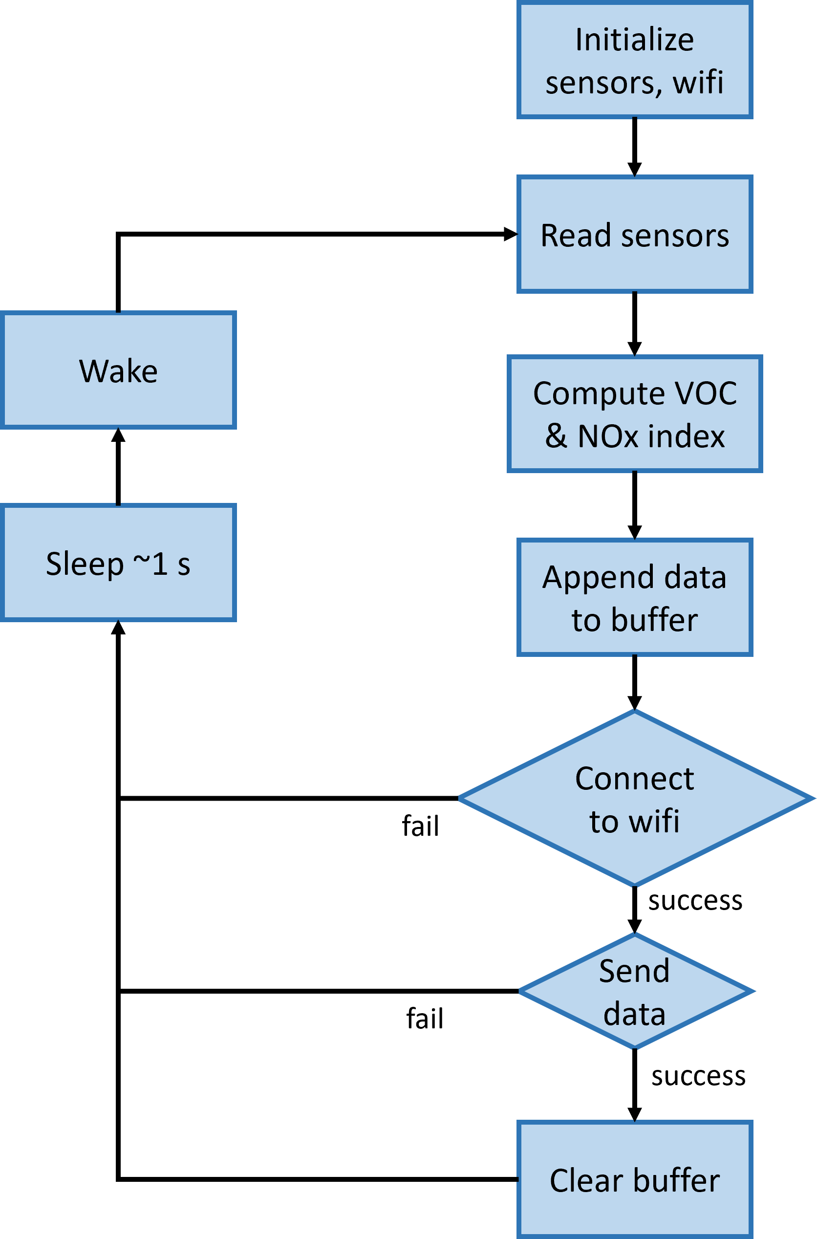
- Firmware in C/C++ via Arduino libraries as needed
- Firmware diagram below
- Comms
- At least WiFi 802.11a/b/g/n 2.4 GHz
- Energy management
- LiPo battery – 18650 w/ JST-PH 2-pin connector
- Lifetime between charging: >12 h
- System voltage: 3.3 V
- Charge from USB-micro connection
- Switch to turn system on and off
- Server
- RPi 3 or 4, one for each student
- SSH access for students and staff
- OS: Raspian, any recent LTS
- Web server: NGINX
- HTTPS GET/POST connections
- DB: SQLite via SQLAlchemy
- Store data perpertually
- Fields: Index number, Timestamp, RH, T, AQ measurements
- No location information transmitted (or stored)
- Server architecture
- See architecture below
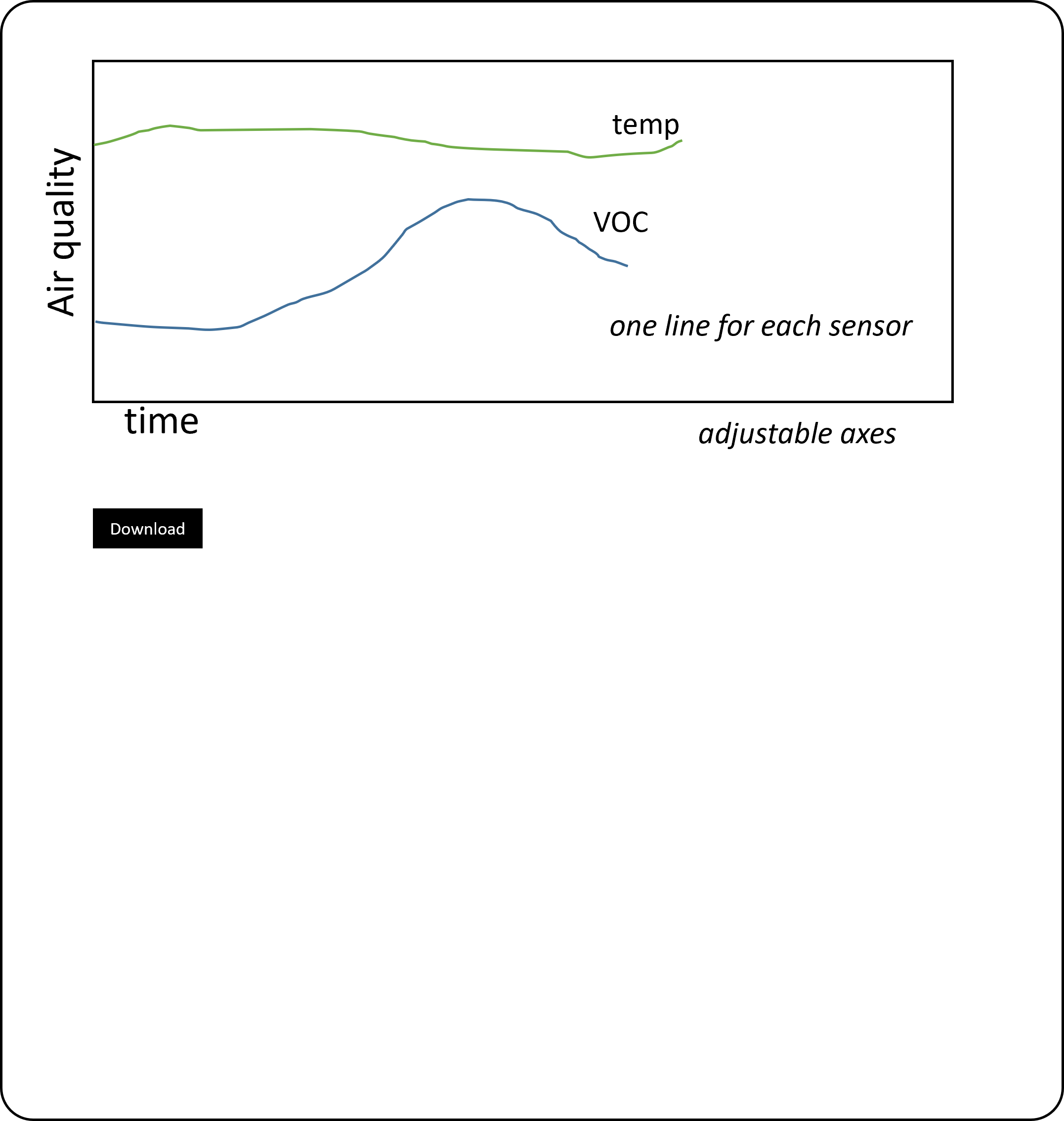
- Web front-end
- Plot.ly
- See wireframe below
- Sensors
- Security & Privacy
- Included above
- Packaging
- Not relevant here
- Installation and servicing
- Hardcoded SSID to connect to EECS-Lab
Here is the current system diagram:
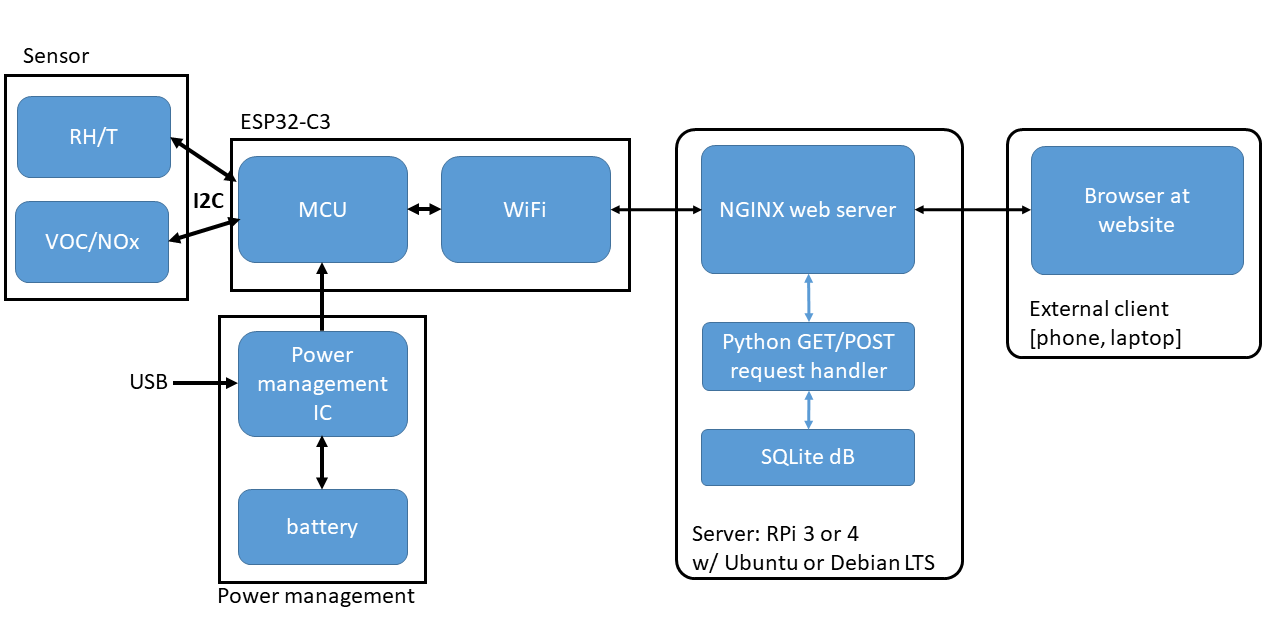
The hardware node for MILO is going to be a small "box" with three circuits boards, one for sensors, one for the MCU, and one for power management. These three boards physically and electrically interact with each other, and the MCU board communicates with the server via the internet.
Each student in the class will design, fabricate, assemble, and test a sensor board. Then within each team, half will design/build an MCU subsystem, and the other half the power management subsystem.
The sensor subsystem will be a PCB that contains two sensor chips, one for temperature & humidity, and one for VOC/NOx. This board needs to communicate with the MCU subsystem to relay data, and with the power subsystem to get power. The sensors need to interact with the outside world, while we want the rest of the subsystem to be protected, which will have impact on the electrical and mechanical designs. The detailed design of that subsystem is in EX01 (schematic capture), Lab02 (schematic design review), EX02 (board layout), and Lab03 (board design review).
The MCU subsystem will be a PCB that contains the microcontroller with associated WiFi module. We'll be using the ESP32-C3 MCU for MILO. It's inexpensive, has easy-to-obtain development boards, has WiFi, and plenty of flash (for code) and RAM (for memory) to make firmware design easier. This board needs to communicate with the sensor subsystem to relay data, and with the power subsystem to get power. The detailed design of this subsystem is in EX02 (schematic capture), Lab03 (schematic design review), EX03 (board layout), and Lab04 (board design review).
The firmware block diagram looks something like:
The Power management subsystem will be a PCB that has several roles: it must be able to send power to the rest of the system, where that power comes either from a battery or the USB port (when plugged in). It should also be able to charge the battery when plugged in. Finally, the board needs to output a well-regulated 3.3V power to the rest of the system.
The detailed design of this subsystem is in EX02 (schematic capture), Lab03 (schematic design review), EX03 (board layout), and Lab04 (board design review).
The server must receive data from the MCU over the Internet via HTTPS GET/POST statements. The server will host a database and a web server. The server must also serve up the dashboard.
The web front-end should show historical data and allow download of the raw data as a csv:
The enclosure will be a 3DP part that must contain all the hardware, including the battery, and should provide visual access to the status LEDs. Connections to charge the battery and update the MCU firmware must be made. We'll need to think about how to expose all those connections (including at least one switch) and the sensors, while protecting the rest of the electronics from the outside world.