Lab 5
Please Log In for full access to the web site.
Note that this link will take you to an external site (https://shimmer.mit.edu) to authenticate, and then you will be redirected back to this page.
Learning Objectives
Today's lab has two goals - assembling your sensor boards, and making sure your Valerie concept is on track. As a result, we'll:
- Solder surface mount parts.
- Have staff inspect your board, get a checkoff.
- Solder through hole parts.
- Test your boards!
- Meet with staff to talk about your development plan for Valerie, get a checkoff.
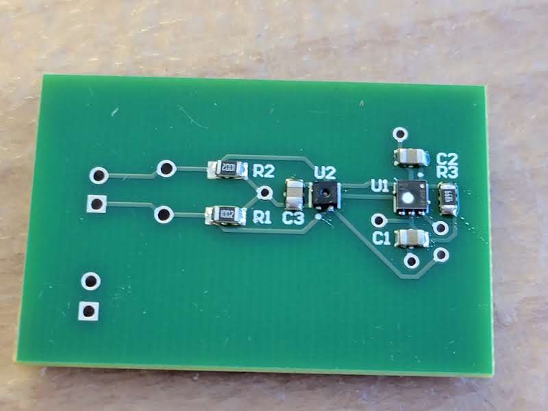
Sensor board assembly
We have our sensor boards back! This is very cool -- these are designs you made and you laid out. Right now we just have the boards themselves, and we'll need to solder components onto them to make them functional circuits. Most of our components are surface mount, so we'll need to use different methods than we'd use for through hole soldering, which you might have done before, like in 6.200. We'll show ya the technique, but first, a note on safety:
Safety
There's a few hazards in soldering:
- Hot Stuff: The soldering iron is really hot, like moreso than Donna Summer's 1979 single. Leaded solder melts at around 370°F give or take depending on what alloy you get, and lead-free melts at around 420°F. As a result the soldering iron has to be at least that temperature, so be careful to not burn yourself! If you drop the iron just let it fall and get out of the way, resist the urge to catch it.
Also be sure to wear safety glasses - I've got friends of friends who've gotten hot beads of solder flicked into their eyes because they were soldering wires under tension. They're blind now. Wear safety glasses.
- Heavy Metals: Traditionally solder is a mix of lead and tin, but since lead's toxic, manufactured goods are required to use lead-free solder instead. The leaded stuff flows a little better and is easier to work with, so it's what we'll use in lab. Lead's super toxic once it gets in your bloodstream, so be super sure to wash your hands after soldering! You don't want to ingest any tiny solder bits. Lead is also pretty soft so you don't have to worry much about stabbing yourself with it and getting some in your blood that way, but just be careful. Holding it in your hands is totally okay though, you don't need gloves or anything as long as you wash 'em afterwards.
-
Solder Paste: We'll be using solder paste today to solder our tiny surface mount components. It's super cool and easy to use, but comes with some extra lead exposure potential. Compared to a spool of solder wire, solder paste is a lot harder to wash off your hands since it can easily work its way into the nooks and crannies of your fingerprints, so we're going to ask that you wear gloves while handling solder paste.
-
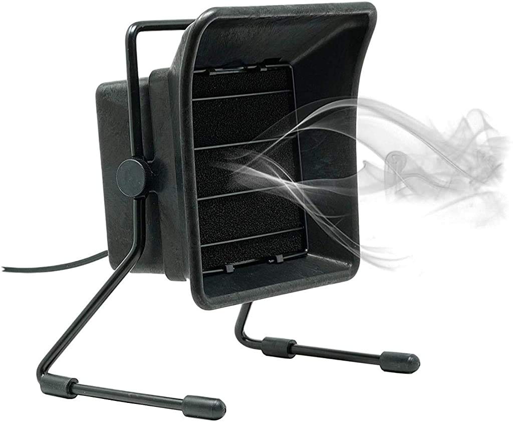
Fumes: When flux boils it gives off a little whiff of white smoke, and breathing that in for a prolonged period of time isn't super good for you. Fume extractors help with this, so we'll be giving you ones like these:
Technique
We'll be using two methods to assemble our sensor boards - one for the surface-mount components, and one for the through-hole connectors. We'll solder the surface mount parts first, then check for any visible errors, and then solder the through hole parts. In our case, the only through hole parts we've got are the JST connectors, which will melt if we hit them with hot air, so we'll be doing those last. Don't ask us how we know that.
We hope that soldering takes no more than an hour of the lab session. If you are struggling, please ask for help!
Surface Mount
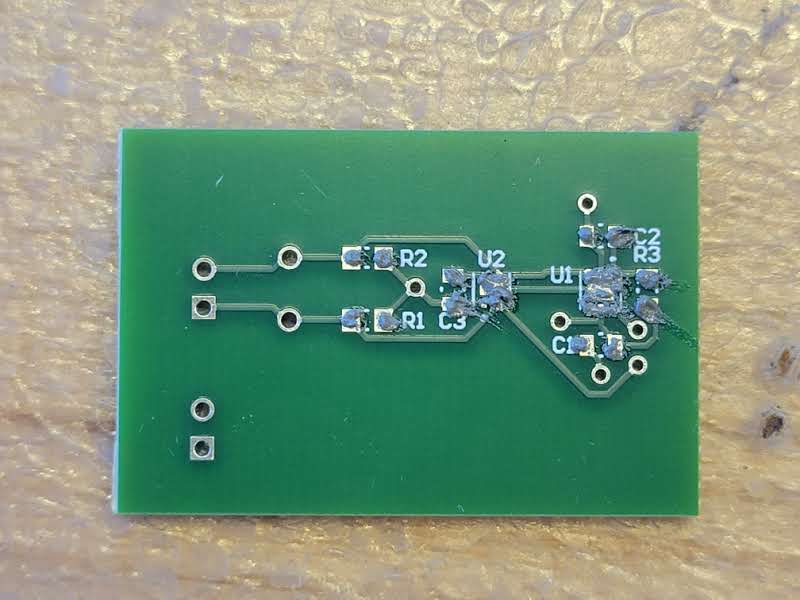
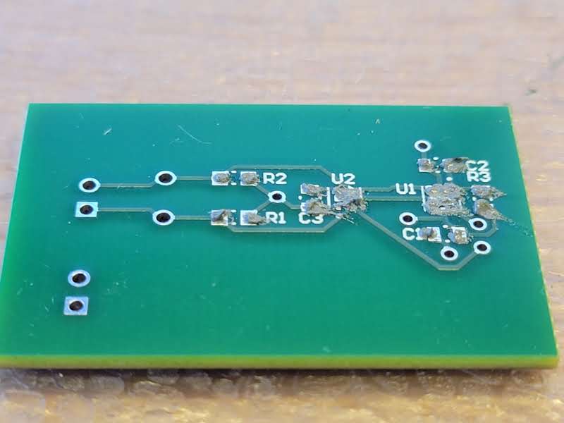
We'll do surface mount by placing a thin bit of solder paste on the exposed pads of the board with a syringe. We don't want this layer to be super thick so we don't short pads by applying too much solder, and it doesn't need to be super precise. Here's about what we're looking for:
Feel free to ask the staff if you'd like a quick check on your paste job!
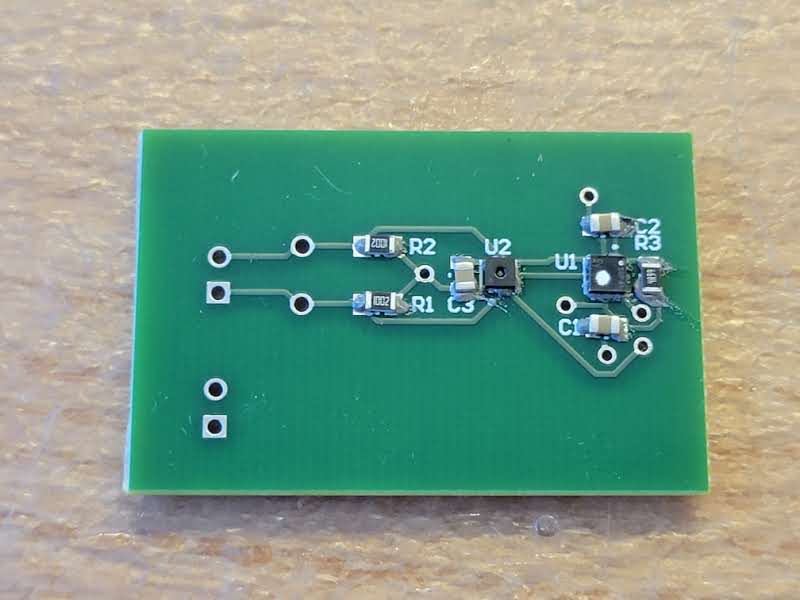
Once you've got your pasted board, place the parts on the pads with tweezers. Be sure to pay attention to the orientation marker on the sensors - the dot on the chip should line up with the dot on the silkscreen. Here's what that looks like:
Once your parts are on the board, take it to a hot air station, and place it on the bed. Do this with tweezers, the beds are hot. Bring the hot air gun over your board, and wait for the solder paste to reflow. It'll go from a dark grey paste to a chaulky light grey, and then to a shiny silver liquid. Once you get to that last step, remove the hot air gun from the top of the board, and wait for it to cool and the solder to solidify. About 2-3 minutes is suffecient.
Checkoff: Visual Inspection
Ask a staff member to look over your assembled board.

Through Hole
The connectors are are through-hole, so if you already know how to solder through hole, go for it! Otherwise, these videos from my friends at SparkFun cover the subject fabulously:
And the written guides from SparkFun and Adafruit are also quite good!
You'll need to solder the JST connectors, and you can optionally solder the through hole testpoints. Those are just a little wire loop that's easy to grab onto with a scope probe, if you ever need to scope that signal.
Testing!
Now let's verify that your sensor board works. There's a good chance that it won't the first time and that's ok! If something seems off, we'll backup and debug with the handy test points you added in your schematic.
First, grab your ESP32 board from Ex04 and plug it in to your computer. The ESP32 has 3.3V and GND pins, so we'll use these for now to power your sensor board. Grab two jumper wires and plug in your sensor board power to your ESP. The first sign of success is that your power indicator LED should turn on. If it doesn't, check your solder connections visually and with a multimeter.
We've set up a test station in lab where you can plug in your sensorboard to an ESP to test that it's working. Before plugging in your sensorboard, unplug the ESP from the computer to unpower it.
Plug in your sensor board SDA and SCL pins to pins 4 and 5 respectively on the ESP. Now plug your ESP back into your computer so both boards are once again receiving power. Your ESP32 should now be attempting to talk to the sensors over the I2C lines. If this is working, your ESP will be printing sensor data to the serial monitor. If it isn't able to talk to the sensors, it should be printing an error message to the serial monitor and you'll have to check your connections on your board.
When you get things working, find a staff member and allow them to join you in celebration of your first working PCB!
Team meeting
Use the remaining lab time to do team work. Part of this is preparing for concept presentations on Mar 23. But also use this time to research, model, and prototype.
At around 1:30, we'll start calling teams back into the conference room to chat for ~10 minutes about your development plan for Valerie. We're going to ask about what open questions exist in your designs, and how you plan on answering them.
Talk to the staff about the next steps you'll make on your design.