Voltage converter choice
Please Log In for full access to the web site.
Note that this link will take you to an external site (https://shimmer.mit.edu) to authenticate, and then you will be redirected back to this page.
Learning Objectives
In this exercise, you'll explore how one might choose to use a buck versus a Low-Dropout voltage converter/regulator.
Voltage conversion
In many electronic systems, including the ones in your semester projects, have a variety of DC (and sometimes AC) voltages (and currents) that are needed to deliver power to various loads in the system. If the voltage going into the system differs from that needed by the load, then we need to adjust that voltage. Ideally, we'd adjust the voltage without any power loss, i.e., with 100% efficiency.
In reality, that's never possible. Converting between one voltage and another will always have some amount of loss/inefficiency involved with it.
When the output DC voltage that you are trying to create is smaller than the input DC voltage, you generally have two choices:
- A linear down-regulator (called an LDO, or "low dropout" regulator)
- A buck converter, a non-linear regulator designed to "step down" the voltage.
Academically speaking, a non-linear regulator will almost always be more efficient than a linear regulator, but that's not the whole story since the cost of a non-linear regulator will often be higher than a linear regulator...so there can be some tough/more-than-one-right decision choices there.
Linear Regulator
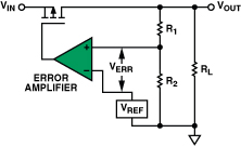
A linear regulator basically acts as a variable resistor, dropping voltage as needed to maintain a stable output voltage, like this figure below from Analog Devices shows very nicely.
Some input voltage V_{IN} is supplied on the left. It is pased through a transistor of some type (often, but not always a power MOSFET as shown here, but always a type of power transistor). The power transistor regulates the current through it based on the voltage applied to its gate (here shown as the bottom terminal). The current flowing through the device largely goes into the "Load" which here is modeled as a resistor R_L. In reality your load will not be a resistor, but perhaps a complicated piece of equipment with time-varying needs (which can be modeled as a time-varying resistance), but for the most part this doesn't matter since the circuit is in negative feedback. The feedback happens via a high-impedance sense path. Resistors R_1 and R_2 take a small amount of current (negligible really...just like you did in monitoring your battery voltage in week 1) and form a voltage divider. That scaled measurement voltage is used with an op amp circuit to compare to a known reference voltage set by the user. The result of that comparison is then used to modify the drive strength applied to the transistor. In this way, the circuit monitors the voltage present on the load and keeps it at some target amount based on the reference voltage. In reality there will usually be some capacitors and other similiar components like lead and lag control and/or PID to smooth out things, but this is a basic feedback system.
The downside of this process though is that during the shades-of-grey control on the transistor, a non-negligble voltage will develop across the transistor (the "drop" voltage). Since all current ultimately delivered to the load goes through that transistor, that means a decent amount of power will be dissipated by the transistor as heat. This isn't great from an energy management perspective. Many linear regulators are specially designed to minimize the minimum voltage drop across that internal resistance. That voltage drop is called the "dropout", and an LDO regulator (or just LDO for short) is one with a small dropout (a hundred mV or so, depending).
Non-Linear Regulator
An alternative to the linear regulator, the buck converter, is shown below. At first glance, it is going to look very similar to the linear regulator. Also like the linear regulator, all current that goes into the load also flows through a power transistor. How the power transistor is used, is important, however. In the case of a linear regulator, the transistor operates in a region where it is neither completely on, nor completely off and as a result it has both non-negligible voltage across it and current through it, which means it will be burning power. In the case of a Buck converter, the transistor is operated either extremely into its "on" mode (in which case it acts like a short-circuit switch with no voltage drop across it but arbitrary current) OR it is extremely into its "off" mode (where it can have arbitrary voltages across it but no current). In both modes, little-to-no power is being dropped across it. Instead an inrush of current is fed into a (often large) inductor during the transistor's "on" phase and then the inductor bleeds off the built up energy during the transistor's "off" phase. The presence of capacitors in the circuit kinda/sorta mushes everythign out with the result of a relatively smooth voltage being present on the load. Also like with the linear regulator, the voltage presented to the load is measured through some sort of high-impedance voltage divider, and this is used in a feedback path to vary how much on vs. off control is applied to the transistor (a pulse-width modulation signal (PWM) signal.). Since, ideally, the current into the load is never going through a dissipative element (the transistor in active mode or a resistor), only being handed back and forth between inductive and capacitive elements which are, at least in theory, lossless, the efficiency of a buck converter can be very high! It is never 100% due to non-idealities, but can get close (into the 90% range).
Analog Devices has more discussion of this here, and you should have learned a bit about them in 6.200, but also go and take Steve Leeb's and Dave Perreault's power electronics classes to get more exposure to this.

In the system we're creating right now, sometimes we want to run off a battery (which will output anyhwere from 3.0 - 4.2 V), and sometimes off USB (which is ~5V). You could also envision wanting to use a solar cell (which has a variety of output voltages). In all cases, the rest of our system components require 3.3V. So we need to regulate the voltage down.
Efficiency
One important consideration in choosing between a buck and an LDO is the efficiency. Let's calculate the efficiency we'd expect to get using two reasonable parts with similar specs:
- Input voltage range of 3.5V to 5.5V
- Output current capability of >600 mA
For the LDO we'll choose the regulator on our ESP32C3-Devkit-M1 board, which is an SG Micro SGM2212 (viewable in the bottom right panel of page 2 of the schematic found here). Here's the datasheet for it.
For the buck, we'll choose the LM3671 that we'll design a board around in the pset. Here's its datasheet.
If you pop open these two datasheets you'll see that the SGM2212 has a huge input range: 2.7 to 20V. Since a linear regulator will ultimately dissipate (in heat) the current supplied multiplied by its voltage drop, if you have a 20V-3.3V drop with a decent amount of current you could be dealing with a ton of heat...this is why the SGM2212 (that you can see on your board and indicated below) is quite large and includes a juicy heatsink-type package.

Also note that 2.7V input voltage is only true if you are using a regulator with a lower output voltage; you're not going to be able to put 2.7V into a 3.3V LDO regulator and expect 3.3V out. If you head over to page 6 of the SGM2212 datasheet you can see the dropout spec. For a 3.3V fixed-output part, the dropout is typically 240 mV when the regulator outputs 500 mA and room temperature (T_J is the temperature of the regulator, which can be hotter than ambient because it heats up as it dissipates power). That means that to create a 3.3V output, you'll need at least 3.54 V input in those conditions.
To compare these parts, let's determine how much power they consume and their efficiency at two extreme conditions:
High power
In this case, we'll assume the input voltage is high (5.0V) and the output current is high (600 mA) -- this would approximate the case when the ESP32 is transmitting WiFi and some peripherals are active, and the system is being powered by USBC. Our output voltage as always is 3.3V.
LDO
The efficiency of the LDO is determined as the output power over the input power. Note that there is some power consumed by the LDO itself, but it is negligible in this case (~80 uA quiescent current).
The dissipated power is difference between the input and output power.

Buck Converter
For the buck converter, the calculations are trickier, and we actually use the datasheet to figure this out. Look through the datasheet and you'll find Figures 13-16. Stare for a while and you'll see the difference between the figures. Use the correct one and you can read off the efficiency. From the efficiency you can back out the dissipated power.
Low Power
In this case, we'll assume the input voltage is low (3.6V) and the output current is low (30 mA) -- this approximates the case when our microcontroller, the ESP32, is just doing calculations (no comms) and the peripherals are mostly quiescent, and the system is being powered by a partially discharged battery.
LDO
Buck Converter
Stepping Back
So we see that the Buck is much more efficient than the LDO at high power, though they become more comparable at low power. At that high power scenario, we were burning up into the W range of power in the LDO. That's really not great for a battery-powered application.
The choice
So why do so many of these boards have LDOs instead of Bucks? Because efficiency is not the only spec we care about. Here are others:
Circuit Complexity
The simplest bucks usually need several external components, including two capacitors and almost always an external inductor. Inductors are big and expensive and they are hard to scale down in general....that's just the physics of them. An LDO circuit, meanwhile just needs two caps and capacitors can be made to be pretty small. So the area of the design might vary, which can be important. Buck converters will often have very specified PCB layout in order to work. They are just a bit more finicky. LDOs just work.
Cost
LDOs are dirt cheap. I found the SGM2212 for about 0.166USD at 1k quantities, whereas the same supplier had the LM3671 for 0.470USD. And the inductor can easily cost similar amount if not more (you cannot pick just any regular inductor off the street...you need to worry about more than just the inductance, but frequency performance, parasitic resistance, and current handling). The LM3671 has a whole section of its datasheet dedicated to picking the right inductor.
Noise and output regulation
LDOs provide a very clean output waveform, whereas switching regulators (like our buck) can create high-frequency noise from that PWM waveform. That can affect downstream electronics. This high frequency noise can exist both in the wire and also "in the air" as general electromagnetic noise. This may motivate one to avoid using an switching supply.
Thermal management
Since LDOs are less efficient, you may need more thermal management to dissipate that power. This can influence the PCB design, overall size, etc. If you need to measure ambient temperature and your board has a LDO that is cooking off heat, you can mess up your measurements. This can even be a problem for non-temperature measurements since many signals and devices are temperature-sensitive to varying degrees.