Lab 1
Please Log In for full access to the web site.
Note that this link will take you to an external site (https://shimmer.mit.edu) to authenticate, and then you will be redirected back to this page.
Before you leave, it's very important to get into the habit of leaving the lab space ready for the next person. So important that we will have future checkoffs specifically for this purpose.
Steps for cleanup:
- Carefully pick up your system and place into a yellow paper envelope.
- Please return the tools (wire strippers, etc.) to staff table.
- Throw away loose wires in your work area.
- Throw away paper, food, etc. in your work area.
Getting Started
You should have already installed Visual Studio Code on your laptop. If you haven't, please do so now from our software install page.
Assembling the embedded system
Today we'll hook up the initial elements of the system. Get the relevant parts from the stash in the middle of the room:
- the ESP32C3 microcontroller board (the same one you used in 6.190x)
- SHT40 breakout board
- bq25185-based power management board
- LiPo battery
- USBC cable
- breadboard
You'll want access to the datasheets, pinouts, and so on for the parts while you do this lab:
- ESP32-C3-DevKitM-1: user guide, pinout, datasheet
- SHT40: datasheet, breakout board
- bq25185: datasheet, breakout board
Some soldering
SHT4x and bq5185 breakout boards
Solder header pins for the bq25185 and sht4x boards.
ESP32 + bq25185 + SHT40
Let's first physically hook up the three boards.
We're going to power the ESP32C3 from the bq25185 board. We'll explain the board in bit more detail later on, but it has two important ICs on it: one that manages power to enable charging a battery or running off a battery, and a second IC that is a 3.3V output buck converter. Even though the ESP32 board has it's own voltage regulator on it, we're going to use the bq25185 power manager board for three reasons:
- it will allow us to go battery-free later on
- it has a nice USB-C connector
- it has a buck converter rather than an LDO regulator, so is a bit more power efficient
Initially, both power and data will come from your laptop over the USB-C cable. We want to provide that power and data to the ESP32 board.
To get the data to the ESP32, we can take advantage of the fact that the bq25185 board breaks out the D+ and D- wires. The most basic USB protocol (USB 2.0) uses the D+/D- wires to send data.
So you just need to wire the bq25185 D+ and D- pins to the USB_D+ and USB_D- pins on the ESP32C3 board.
This approach actually has a nice benefit -- it's bypasses the ESP32C3 breakout board's USB-to-UART bridge (a chip that interfaces between your laptop's USB and the ESP32C3's UART pins) and instead connects directly to the ESP32C3's on-board USB.
To get power to the ESP32 and bypass it's on-board regulator, we can use the 3V and G pins on the bq25185 board. The G pin is the GND pin, and the 3V pin is the regulated 3.3V output of the buck converter. So when powered via USB, this board will take the 5V USB power and convert it down to 3.3V. Just connect these to the 3V3 and GND pins on the ESP32 board.
The other board to connect up is the SHT40 breakout board. This one we're going to let you figure out a bit. Take a look at the pinout for the ESP32C3 and the pinout for the SHT40 breakout to figure out the connections you need to make.
Then make those connections.
Some notes:
- Please keep your wires flat, neat, and short. Use color coding for ground, 3V3, signals, etc. Trim capacitor and resistor leads so the components are neat.
- Now's a good time to give yourself power (3.3V, not 5V!) and ground rails on your breadboard. They will come in handy later.
- Where are those I2C pins on the ESP32? Turns out you can use any two GPIO pins for I2C. Pick two that are convenient. But don't use GPIO8/9 or GPIO20/21.
When you're ready, connect your system to your laptop with a USB cable via the USB-C connector on the bq25185 board, and if you did it right you should see green LEDs light up on the bq25185 & sht4x boards, along with a blinky yellow/orange on on the bq25185 board, and very likely the RGB LED on the ESP32C3 board.
Show your wired-up system to a staff member.

Getting some code running
Now let's actually get something running on our microcontroller to see if our software is working. Although we're going to use VS Code and PlatformIO, we aren't going to use the GUI, we're going to go thru the command-line interface (CLI), because it is faster.
Open a terminal and navigate to a directory where you'd like to store your lab01 code. You'll want to make an empty directory for that, and navigate into it.
To initialize your project, type:
pio project init --board esp32-c3-devkitm-1
This should take a few seconds and spit out a bunch of stuff into the terminal, like so:
The following files/directories have been created in C:\Users\Joel\Dropbox (MIT)\MIT\Teaching\6.900-S25\code\lab01
include - Put project header files here
lib - Put project specific (private) libraries here
src - Put project source files here
platformio.ini - Project Configuration File
Resolving esp32-c3-devkitm-1 dependencies...
Tool Manager: Installing platformio/tool-scons @ ~4.40801.0
Downloading  [####################################]  100%
Unpacking  [####################################]  100%
Tool Manager: tool-scons@4.40801.0 has been installed!
Tool Manager: Removing tool-scons @ 4.40700.0
Tool Manager: tool-scons@4.40700.0 has been removed!
Already up-to-date.
Project has been successfully initialized!
platformio.ini, your project configuration file
Next, we need to tell the compiler to use the ESP32C3's on-board USB interface.
Open platformio.ini in your favorite IDE/editor. This will be the configuration file for your project.
You should see these four lines:
[env:esp32-c3-devkitm-1]
platform = espressif32
board = esp32-c3-devkitm-1
framework = arduino
Add the following lines to this file:
[env:esp32-c3-devkitm-1]
platform = espressif32
board = esp32-c3-devkitm-1
framework = arduino

build_flags =
  -DARDUINO_USB_MODE
  -DARDUINO_USB_CDC_ON_BOOT
Save the file and close it.
main.cpp, where your program lives
In your terminal, navigate to the src folder, which should be empty. Create a file called main.cpp in your favorite IDE (could be VS Code if you wish). Instead of using the standard int main(void) C-type function entry, we'll instead use the Arduino.h library to allow us to use the setup and loop functions common to that way of programming. As a reminder, since we'll assume you've all done some Arduino-type programming before:
setupruns once at the beginning of the program and we'll use it for a lot of initializations.loopruns continuously as fast as it can/we allow it. This is where the microcontroller will "live" most of the time.
Within main.cpp, copy and paste the following code:
#include <Arduino.h>

void setup() {
  Serial.begin(9600);
}

void loop() {
  Serial.printf("Hello World");
  delay(1000);
}
Let's "use" it. First, we need to build the code.
Back in your terminal, use the following command to build:
pio run
This should take a few seconds. If the code compiled successfully, you should see a message saying something like "[SUCCESS] Took 45 seconds" print out in the terminal.
Upload
Next, making sure that you have physically connected your ESP32 to your computer, use the following command to build and upload the project to the ESP32:
pio run --target upload
Again, after a few seconds you should see the [SUCCESS] message.
Serial monitor
The code above should be printing to the serial monitor. So let's take a look, again via the CLI.
In your terminal, type:
pio device monitor
You should now see Hello World printed over and over.
Let's sense some temp
Find the Adafruit SHT40 library
Rather than write our own I2C library to interface with the SHT40, we're going to use a pre-written one by Adafruit. But we need to find it and tell platformIO to install and use it.
We can search for libraryies use the platformIO CLI. It's a bit more cumbersome than the GUI, but let's try it nonetheless. For example:
pio pkg search "sht4x"
will return a list of possible packages that include the word "sht4x" in the title. SHT40 is one of several almost equivalent parts denoted by SHT4x.
You should see the adafruit library in that list. You'll also notice that the version number is 1.0.5.
Open up the platformio.ini file from before and add the following lines to the end of the file:
lib_deps =
  adafruit/Adafruit SHT4x Library @ ^1.0.5
  SPI
This tells platformIO which libraries you are using in your project, and it will automatically install them if needed.
You can see that the first part of this line is the library name, exactly as noted in the terminal. Then we have the @ character, telling platformIO that we want to specify a version of the library (this is recommended practice) and then ^1.0.5 saying to use version 1.0.5 or higher.
To refer to that library in your code, you'll add an #include directive in your main.cpp pointing to the header file for that library. To get that header file name, I typically find the library on github or wherever it is and look up the header file name. In this case it is Adafruit_SHT4x.h.
Now, let's get some basic code running. Copy/paste the following into your main.cpp:
#include <Arduino.h>

#include "Adafruit_SHT4x.h"

#define I2C_SDA 4
#define I2C_SCL 5

Adafruit_SHT4x sht4 = Adafruit_SHT4x();

void setup() {
  Serial.begin(115200);
  while(Serial == false){};  // Wait for the serial connection to startup
  Serial.println("SHT40 Example 1 - Basic Readings");    // Title
  Wire.begin(I2C_SDA, I2C_SCL);

  if (! sht4.begin()) {
    Serial.println("Couldn't find SHT4x");
    while (1) delay(1);
  }

  Serial.println("Found SHT4x sensor");
  Serial.print("Serial number 0x");
  Serial.println(sht4.readSerial(), HEX);

  // You can have 3 different precisions, higher precision takes longer
  sht4.setPrecision(SHT4X_HIGH_PRECISION);
  switch (sht4.getPrecision()) {
     case SHT4X_HIGH_PRECISION:
       Serial.println("High precision");
       break;
     case SHT4X_MED_PRECISION:
       Serial.println("Med precision");
       break;
     case SHT4X_LOW_PRECISION:
       Serial.println("Low precision");
       break;
  }

  // You can have 6 different heater settings
  // higher heat and longer times uses more power
  // and reads will take longer too!
  sht4.setHeater(SHT4X_NO_HEATER);
  switch (sht4.getHeater()) {
     case SHT4X_NO_HEATER:
       Serial.println("No heater");
       break;
     case SHT4X_HIGH_HEATER_1S:
       Serial.println("High heat for 1 second");
       break;
     case SHT4X_HIGH_HEATER_100MS:
       Serial.println("High heat for 0.1 second");
       break;
     case SHT4X_MED_HEATER_1S:
       Serial.println("Medium heat for 1 second");
       break;
     case SHT4X_MED_HEATER_100MS:
       Serial.println("Medium heat for 0.1 second");
       break;
     case SHT4X_LOW_HEATER_1S:
       Serial.println("Low heat for 1 second");
       break;
     case SHT4X_LOW_HEATER_100MS:
       Serial.println("Low heat for 0.1 second");
       break;
  }

}


void loop() {
  sensors_event_t humidity, temp;

  uint32_t timestamp = millis();
  sht4.getEvent(&humidity, &temp);// populate temp and humidity objects with fresh data
  timestamp = millis() - timestamp;

  Serial.print("Temperature: "); Serial.print(temp.temperature); Serial.println(" degrees C");
  Serial.print("Humidity: "); Serial.print(humidity.relative_humidity); Serial.println("% rH");

  Serial.print("Read duration (ms): ");
  Serial.println(timestamp);

  delay(1000);
}
Go thru the code and make sure you can figure out what it's doing. You'll want to update the code to your exact I2C pins. The numbers refer to the GPIO pins, aka "6" is GPIO6 not pin 6.
Build, then Upload the project usin the PlatformIO command line, and look at the serial monitor. If all is well (wiring, library, etc.) you should see the humidity and temperature printing out like so (obviously different based on where you are at on this big blue marble which we only have one of don't you know so let's take care of it)
Temperature: 22.66 degrees C
Humidity: 83.01% rH
Read duration (ms): 11
Temperature: 22.62 degrees C
Humidity: 81.95% rH
Read duration (ms): 11
...
If it isn't printing or giving errors in readout, double check your wiring, and all the other usual suspects one would think about with a sysytem like this. Also, of course, reach out for help on Piazza or with staff!
Do some stuff to make sure those readings make sense and change as a result of perturbations.
To the internet!
Ok instead of having our device read a local sensor, let's instead talk to a server via the internet. Let's replace our code with the code below.
Note a few things:
- There's a lot more going on in this code than the previous two. (It is basically a modified version of some 6.08 code from a lab).
- This code connects to the WiFi. This requires you to put in the valid credentials for a 2.4GHz network. The good ones on the 5th floor lab space (hopefully where you are) are either
EECS_Labs(with no password) or608_24Gwith password608g2020. - To use the campus-wide
MITnetwork, you must first register for a personal password at the MIT wifi onboarding portal. Once you register you can put your personal password in the ESP code along with theMITssid - Once connected this code will send simple HTTP GET requests to a remote server that provides number-based facts in response.
You'll also need to now comment out the lib_deps section of your platform.ini since you are not using that here:
;lib_deps =
; adafruit/Adafruit SHT4x Library @ ^1.0.5
; SPI
#include <Arduino.h>
#include <WiFi.h> //Connect to WiFi Network
#include <string.h>  //used for some string handling and processing.

void do_http_GET(char* host, char* request, char* response, uint16_t response_size, uint16_t response_timeout, uint8_t serial);
uint8_t char_append(char* buff, char c, uint16_t buff_size);

const int RESPONSE_TIMEOUT = 30000; //ms to wait for response from host
const int GETTING_PERIOD = 5000; //periodicity of getting a number fact.
const uint16_t IN_BUFFER_SIZE = 1000; //size of buffer to hold HTTP request
const uint16_t OUT_BUFFER_SIZE = 1000; //size of buffer to hold HTTP response
char request_buffer[IN_BUFFER_SIZE]; //char array buffer to hold HTTP request
char response_buffer[OUT_BUFFER_SIZE]; //char array buffer to hold HTTP response

uint32_t last_time=0; //used for timing

//wifi network credentials for 6.08 Lab (this is a decent 2.4 GHz router that we have set up...try to only use for our ESP32s)
char network[] = "608_24G";
char password[] = "608g2020";


void setup() {
  Serial.begin(9600); //begin serial
  while (!Serial) {
      delay(100);
  }

  WiFi.begin(network, password);
  //if using channel/mac specification for crowded bands use the following:
  //WiFi.begin(network, password, channel, bssid);
  uint8_t count = 0; //count used for Wifi check times
  Serial.print("Attempting to connect to ");
  Serial.println(network);
  while (WiFi.status() != WL_CONNECTED && count < 6) { //can change this to more attempts
    delay(500);
    Serial.print(".");
    count++;
  }
  delay(2000);  //acceptable since it is in the setup function.
  if (WiFi.isConnected()) { //if we connected then print our IP, Mac, and SSID we're on
    Serial.println("CONNECTED!");
    delay(500);
  } else { //if we failed to connect just Try again.
    Serial.println("Failed to Connect :/  Going to restart");
    Serial.println(WiFi.status());
    ESP.restart(); // restart the ESP (proper way)
  }
  randomSeed(analogRead(A0)); //"seed" random number generator
}

/*-----------------------------------
  Generate a request to the numbersapi server for a random number
  Display the response both on the TFT and in the Serial Monitor
*/
void loop() {
  if ((millis() - last_time) > GETTING_PERIOD) { // GETTING_PERIOD since last lookup? Look up again
    //formulate GET request...first line:
    sprintf(request_buffer, "GET http://numbersapi.com/%d/trivia HTTP/1.1\r\n", random(200));
    strcat(request_buffer, "Host: numbersapi.com\r\n"); //add more to the end
    strcat(request_buffer, "\r\n"); //add blank line!
    //submit to function that performs GET.  It will return output using response_buffer char array
    do_http_GET("numbersapi.com", request_buffer, response_buffer, OUT_BUFFER_SIZE, RESPONSE_TIMEOUT, true);
    last_time = millis();//remember when this happened so we perform next lookup in GETTING_PERIOD milliseconds
  }
}


/*----------------------------------
   char_append Function:
   Arguments:
      char* buff: pointer to character array which we will append a
      char c:
      uint16_t buff_size: size of buffer buff

   Return value:
      boolean: True if character appended, False if not appended (indicating buffer full)
*/
uint8_t char_append(char* buff, char c, uint16_t buff_size) {
  int len = strlen(buff);
  if (len > buff_size) return false;
  buff[len] = c;
  buff[len + 1] = '\0';
  return true;
}

/*----------------------------------
   do_http_GET Function:
   Arguments:
      char* host: null-terminated char-array containing host to connect to
      char* request: null-terminated char-arry containing properly formatted HTTP GET request
      char* response: char-array used as output for function to contain response
      uint16_t response_size: size of response buffer (in bytes)
      uint16_t response_timeout: duration we'll wait (in ms) for a response from server
      uint8_t serial: used for printing debug information to terminal (true prints, false doesn't)
   Return value:
      void (none)
*/
void do_http_GET(char* host, char* request, char* response, uint16_t response_size, uint16_t response_timeout, uint8_t serial) {
  WiFiClient client; //instantiate a client object
  if (client.connect(host, 80)) { //try to connect to host on port 80
    if (serial) Serial.print(request);//Can do one-line if statements in C without curly braces
    client.print(request);
    memset(response, 0, response_size); //Null out (0 is the value of the null terminator '\0') entire buffer
    uint32_t count = millis();
    while (client.connected()) { //while we remain connected read out data coming back
      client.readBytesUntil('\n', response, response_size);
      if (serial) Serial.println(response);
      if (strcmp(response, "\r") == 0) { //found a blank line! (end of response header)
        break;
      }
      memset(response, 0, response_size);
      if (millis() - count > response_timeout) break;
    }
    memset(response, 0, response_size);  //empty in prep to store body
    count = millis();
    while (client.available()) { //read out remaining text (body of response)
      char_append(response, client.read(), OUT_BUFFER_SIZE);
    }
    if (serial) Serial.println(response);
    client.stop();
    if (serial) Serial.println("-----------");
  } else {
    if (serial) Serial.println("connection failed :/");
    if (serial) Serial.println("wait 0.5 sec...");
    client.stop();
  }
}
Upload the code. In the serial monitor, you should see random number facts printing out every few seconds. Your ESP32 does not internally contain all those facts, so the only way it could be printing those would be if it was getting them through the "ether"...so WiFi must be working. Nice. If you have that, that means you're good to move on!
Connecting our sensor to the internet
Now let's combine these two prior pieces of code to be able to post your sensor data to the internet. You'll need to read through and understand what the code is doing in order to know how to combine. Simply concatenating the code will not work!
You'll want to update your loop function to create a POST request instead of a GET request. Though it's cooler to use a POST body to submit your data, for now we'll use query arguments since it's a touch simpler.
Here are the specs:
- You code should set up the sht4x sensor
- In the
loopfunction, you want to make a RH/T measurement and then send that data to a server. - The host you are trying to reach is efpi-10.mit.edu
- You need to convert your RH and T readings from floats to char arrays. sprintf(), similar to what's shown below, is a good way to do that.
- You need to add your kerberos as a parameter.
You can use the query arguments to convey your data (don't need to use a POST body for this one, though you can if you'd like). The important thing though is to use the POST http verb to post data (as opposed to the GET verb we used earlier)
POST /efi_test/logger?temp=70.49&rh=30.54&kerberos=None HTTP/1.1
You actually don't need to change your do_HTTP_GET function, as it doesn't actually care whether it sends a GET or a POST.
void loop() {
  if ((millis() - last_time) > GETTING_PERIOD) { // GETTING_PERIOD since last lookup? Look up again
    //formulate GET request...first line:
    sprintf(request_buffer, "GET http://INSERT_SERVER_AND_STRINGS_HERE HTTP/1.1\r\n", thing1, thing2);
    strcat(request_buffer, "Host: INSERT_SERVER_HERE\r\n"); //add more to the end
    strcat(request_buffer, "\r\n"); //add blank line!
    //submit to function that performs GET.  It will return output using response_buffer char array
    do_http_GET("INSERT_SERVER_HERE", request_buffer, response_buffer, OUT_BUFFER_SIZE, RESPONSE_TIMEOUT, true);
    Serial.println(response_buffer); //print to serial monitor
    last_time = millis();//remember when this happened so we perform next lookup in GETTING_PERIOD milliseconds
  }
}
You'll also need to now uncomment the Adafruit library in your platformio.ini file.
Once you've worked out what the code should be, recompile, reupload, and then see what happens in the serial monitor. Eventually, your code should repeatedly start printing this:
POST http://efpi-10.mit.edu/efi_test/logger?temp=70.82&rh=24.82&kerberos=None HTTP/1.1
Host: efpi-10.mit.edu

HTTP/1.1 200 OK
Server: nginx/1.18.0
Date: Tue, 23 Jan 2024 21:51:51 GMT
Content-Type: text/html; charset=utf-8
Content-Length: 6
Connection: keep-alive

posted
-----------
Once you are getting a "posted" return message, you can check to see your data on the server. Point your browser to:
http://efpi-10.mit.edu/efi_test/reporter?kerberos=None
And all your data should list out.
Show your system posting to the server to a staff member.
Look ma no wires
Being hooked up to the laptop all the time is very mid. We can send our data to our cloud server, so let's also go wireless with the power, aka let's go battery-powered.
We'll power our system via a LiPo battery. A single-cell LiPo battery has a nominal voltage of 3.7V (a bit more when fully charged, and decreasing as it discharges).
But eventually the battery will discharge, so we need a way of charging it back up. So we need some sort of integrated circuit to charge the battery. LiPo batteries can be dangerous, so specialized ICs are used to make sure the batteries charge at the right rate and to the right voltage.
But it gets even more complicated. If we're running off of the battery, and the battery gets too discharged, we'd like to be able to plug the system in, and have the system continue working, while the battery is charging. After all, when you plug your phone in to charge, you expect the phone's battery to charge and the phone to still work.
So really what we need is some magical IC (or ICs) to manage the power, directing power to/from the battery, to the system, from the wall, and so on. Sounds complicated.
Luckily, it's complicated but extremely commonly needed, and hence companies have created solutions to do this. These systems go under various interrelated name: battery management system (BMS), power management IC (PMIC), battery chargers, and so on.
That's part of what our Adafruit bq25185 breakout board does. The bq25185 chip on this board (~$1.20! at our quantities), includes "load sharing" (aka automatically directing power to the system or the battery), and battery charge management (charge the battery). That board also includes a 3.3V buck converter on it to provide a nice regulated system voltage for the rest of our system.
Basically, the system operates in a few different modes:
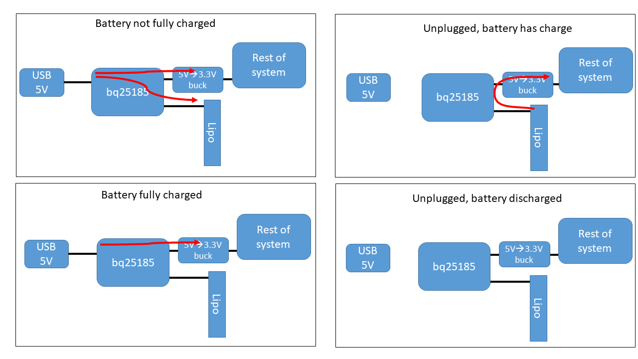
Since you've already hooked up your bq25185 breakout board, all you need to do is connect your LiPo battery to the battery connector on the board (this is a type of "JST" connector, if you want to be cool about it).
When you make that connection, if you are connected to USB, you should be charging the battery (the orange LED should be on). The orange LED will turn off when the battery is fully charged. If you now disconnect the USB cable, your green LEDs should stay on, meaning that you are powering your system off the battery. Very cool.
There's also a red LED. If that light's up, something went wrong. The Adafruit website for the board tells us what each LED means.
If this is all working, check the website. Should be posting data. Congrats, you have a battery-powered IoT weather station!
Now, you really have a go-to system.
Show your battery-powered system posting to the server to a staff member.
Sensing battery voltage
At this point we should have a battery powered portable temperature/humidity sensor. One key element of battery-powered systems is knowing how much charge is left in the battery. This is known as the battery state of charge (SOC), and ranges between 0% and 100%. It's super annoying if the only way to know the battery SOC is when the system just dies (which just tells you the SOC is 0%, great).
So let's add battery sensing capabilities to our system.
Measuring the charge left in a LiPo battery is actually not trivial. In fact, it's so difficult to do that companies make dedicated ICs (called fuel gauges) to do so. And we'll develop our own fuel gauge board in a few weeks.
But we can get a rough sense by just measuring the battery voltage. The battery's voltage can range between 4.2 volts (100% SOC) and 3.4 volts (~0% SOC).
Where can we get access to the battery voltage directly? Not the 3V pin on the bq25185 board, as that is a regulated output. But you'll notice there's a BAT pin on that board, and, as you guessed, it is directly connected to the battery. So we just need to measure that voltage!
But wait. One of the challenges with doing this directly is that the ESP32's adc can only measure voltages between 0V and 2.5V. But the battery voltage is going between 3.4 Vand 4.2 V. We need to somehow scale that voltage down to a max of 2.5V (otherwise our ESP would just read 2.5V).
We can use a pair of resistors to make a voltage divider. We can then safely measure the scaled down voltage, in our code apply the inverse of our divider ratio, and arrive at the true pre-divider voltage measurement.
So lets just grab any two resistors off the floor, hook up our battery, and fix it in software. Not so fast.
-
We can't just use any two resistors. These two resistors will be permanently attached to our battery. If their resistance is too low, they will quickly discharge our battery, shorten our run-time, and may even turn into an LER. We should design our divider to draw less than 1mW of power (which is still kind of a lot, but ok for now).
-
The ESP's adc will draw a (very) small amount of current from the output of the resistor divider. Make sure that the equivalent Thévenin resistance of the divider presents a negligible (<10mV) drop when the ESP's adc draws it's sampling current (1uA).
One last hardware thing. We should add a capacitor to the output of the voltage divider to smooth out the voltage measurement. This value is not as critical as the resistors from above. Anything between 1nF and 10uF should work.
Analog to digital conversion
Now that we have conditioned the voltage signal, connect the output of the divider to an available analog GPIO of our ESP32. We wrote some code to help you extract the raw ADC value from the ESP and convert it to a voltage.
/* NOTE: paste the following line at the top of your main.cpp*/
#include "esp_adc_cal.h"
/*                    */


/*----------------------------------
   read_analog_voltage Function:
   Arguments:
      int gpio_pin: GPIO pin number from which to read the analog value
      int num_average: Number of readings to average for smoothing the output
   Return value:
      float: Returns the average voltage reading from the specified GPIO pin in volts
*/
float read_analog_voltage(int gpio_pin, int num_average)
{
  esp_adc_cal_characteristics_t adc_chars; // Structure to store ADC calibration characteristics
  int adc_readings_raw = 0;                // Variable to accumulate raw ADC readings

  // Loop to collect multiple ADC readings for averaging
  for (int i = 0; i < num_average; i++)
  {
    adc_readings_raw += analogRead(gpio_pin); // Add current reading to total
    delayMicroseconds(10);                    // Tiny delay to allow for ADC settling
  }
  adc_readings_raw = adc_readings_raw / num_average; // Calculate average of readings

  // Determine the ADC unit based on the GPIO pin number
  adc_unit_t current_adc = ADC_UNIT_1; // Default ADC unit
  if (gpio_pin == 5)
  {
    current_adc = ADC_UNIT_2; // Change ADC unit for specific pins, if necessary
  }

  // Characterize the ADC at 11 dB attenuation and 12-bit width for accurate voltage conversion
  esp_adc_cal_characterize(current_adc, ADC_ATTEN_DB_11, ADC_WIDTH_BIT_12, 1100, &adc_chars);

  // Convert the average raw reading to voltage in volts, using calibration characteristics
  return (esp_adc_cal_raw_to_voltage(adc_readings_raw, &adc_chars) / 1000.0);
}
This function takes the GPIO number of the analog pin and returns a floating point value of the voltage present on that pin. It will sample the pin num_average times and average the result.
This function then returns the voltage present on the specified analog GPIO pin. Make sure to "undivide" the voltage divider ratio to get the actual battery voltage.
Incorporate this functionality into your code, and make sure your system is correctly measuring voltage (get a multimeter and actually confirm). It should be reasonably close (within 5%). Depending on your battery's charge, your system should measure a voltage between 3.4 and 4.2 volts. If your system is charging, it might read up to ~5 volts.
Going from voltage to SOC is not trivial, as mentioned above. That's because the LiPo discharge curve is very flat (see an example here. So small errors in the measurement of the voltage lead to large errors in estimate of the SOC. This is why there are dedicated ICs that implement various strategies and sophistcated algorithms to do this. For now, we're just going to report the battery voltage. We'll get fancier in a few weeks.
Tying it all together
Let's finish this lab.
Your final system should still make POST requests with the temperature and humidity as it did above. Now, add another query argument bat for the battery voltage. When all is said and done, your system should make a request with 4 query arguments:
- temp=...
- rh=...
- kerberos=...
- bat=...
Once you see your data being posted to the server and can view it on the webpage, you'r finished! In EX01 we'll change from the efpi-10 endpoint to your own server, and use those logs to verify that your system is working.
Show your battery-powered system posting your data including battery voltage to the server to a staff member.