Lab 5
Please Log In for full access to the web site.
Note that this link will take you to an external site (https://shimmer.mit.edu) to authenticate, and then you will be redirected back to this page.
Learning Objectives
Today's lab will focus on assembling and testing your sensor boards. We'll:
- Solder some surface mount parts.
- Have staff inspect your board, get a checkoff.
- Solder the remaining surface mount parts.
- Solder through-hole parts.
- Test your boards!
- Get another checkoff.
Plugin Installation
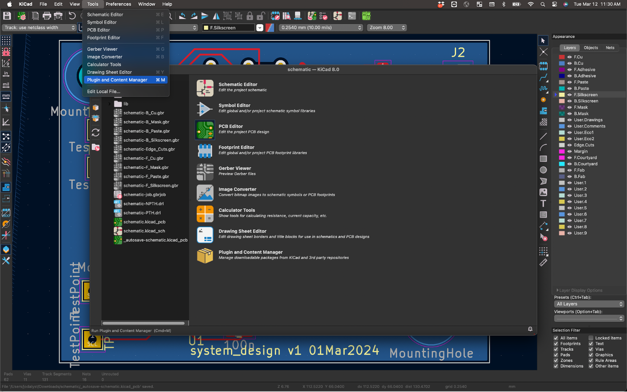
KiCad has a really neat plugin that can be activated which provides an easy-to-read "GUI" of your board and its components and elements. It can be very helpful in the assembly that you'll be doing. To install, first go into your main KiCad page and Tools -> Plugin and Content Manager.
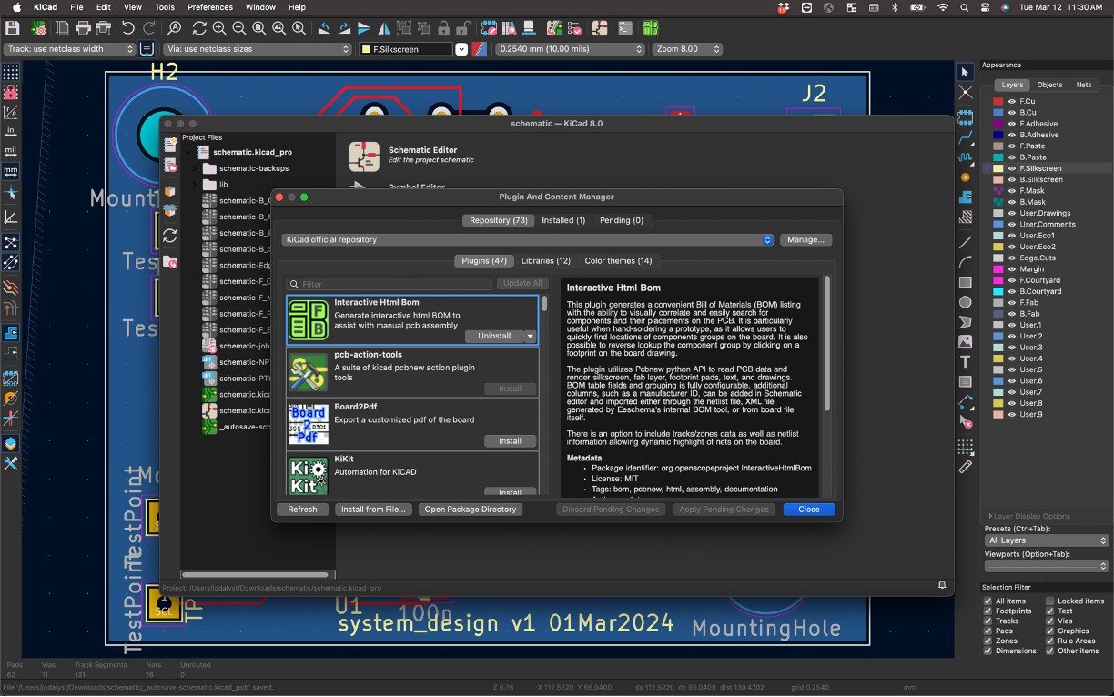
In there, look for the Interactive HTML BOM plugin. Install it.
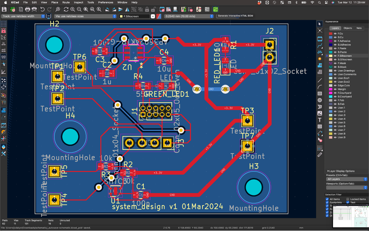
Once installed open up your PCB that you want to use with the plugin. In the top panel there should now be a bright-green button you can push corresponding to this plugin. Click it.
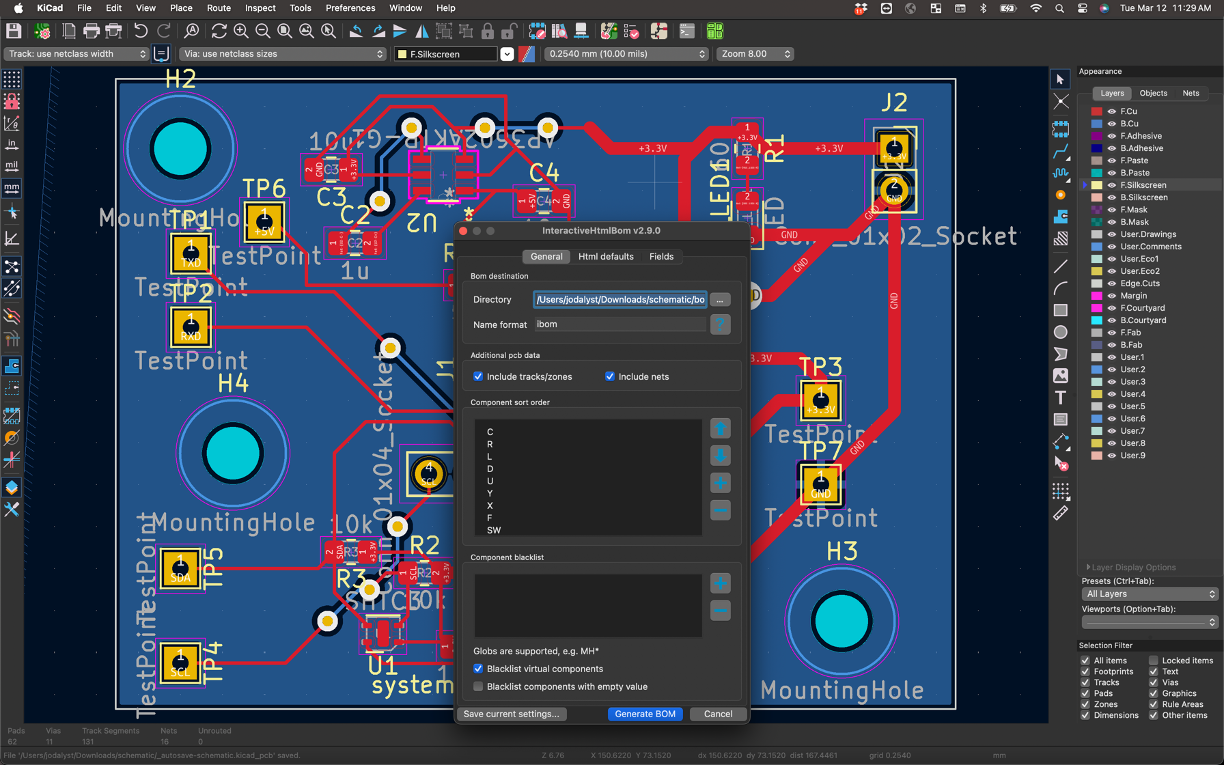
In the window that comes up, make sure to check the options about including nets and traces. When ready, then go and click Generate BOM.
You should be transferred to your web browser (hopefully it doesn't block this) and it'll present you with a web page that is your board along with all your components. There's different features you can look at including parts that need to be assembled:
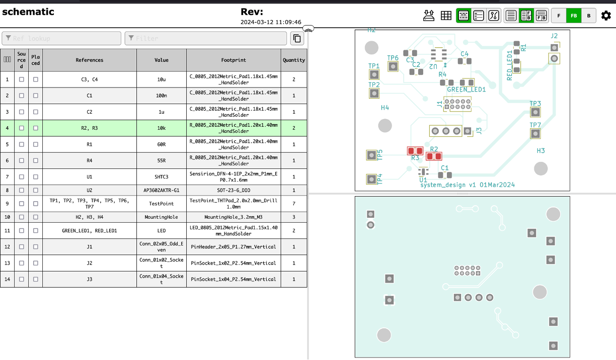
As well as your traces and other angles of your board.

This tool can be really help when assembling since it will tell you what parts go where in a very easy-to-read and visualize manner.
Sensor board assembly
We have our sensor boards back! This is very cool -- these are designs you made and you laid out and you messed up (jk...hopefully). Right now we just have the boards themselves, and we'll need to solder components onto them to make them functional circuits. Most of our components are surface mount, so we'll need to use different methods than we'd use for through-hole soldering, which you might have done before, like in 6.200. There is a box of all of the sensorboards on the table in our lab space. The packaging for each of your boards is labeled with GerberFile:fab-[kerb] at the bottom, so make sure you grab YOUR boards.
We'll show you the techniques, but first, a note on safety:
Safety
There's a few hazards in soldering:
- Hot Stuff: The soldering iron is really hot, like moreso than Donna Summer's 1979 single. Leaded solder melts at around 180°C (356°F) give or take depending on what alloy you get, and lead-free melts at around 220°C (~420 °F). As a result the soldering iron has to be at least that temperature, so be careful to not burn yourself! If you drop the iron just let it fall and get out of the way, resist the urge to catch it.
Also be sure to wear safety glasses - I've got friends of friends who've gotten hot beads of solder flicked into their eyes because they were soldering wires under tension. They're blind now. Wear safety glasses.
- Heavy Metals: Traditionally solder is a mix of lead and tin, but since lead's toxic, manufactured goods are required to use lead-free solder instead. The leaded stuff flows a little better and is easier to work with, so it's what we'll use in lab. Lead's super toxic once it gets in your bloodstream, so be super sure to wash your hands after soldering! You don't want to ingest any tiny solder bits. Lead is also pretty soft so you don't have to worry much about stabbing yourself with it and getting some in your blood that way, but just be careful. Holding it in your hands is totally okay though, you don't need gloves or anything as long as you wash 'em afterwards.
-
Solder Paste: We'll be using solder paste today to solder our tiny surface mount components. It's super cool and easy to use, but comes with some extra lead exposure potential. Compared to a spool of solder wire, solder paste is a lot harder to wash off your hands since it can easily work its way into the nooks and crannies of your fingerprints, so we're going to ask that you wear gloves while handling solder paste. Also make sure when done to especially wash your hands! You should do that with regular spooled solder too, but the solder paste really can get on lots of stuff. The solder paste can be found in the 6.9000 parts organizer. Please put it back in the organizer when you are done using it.
-
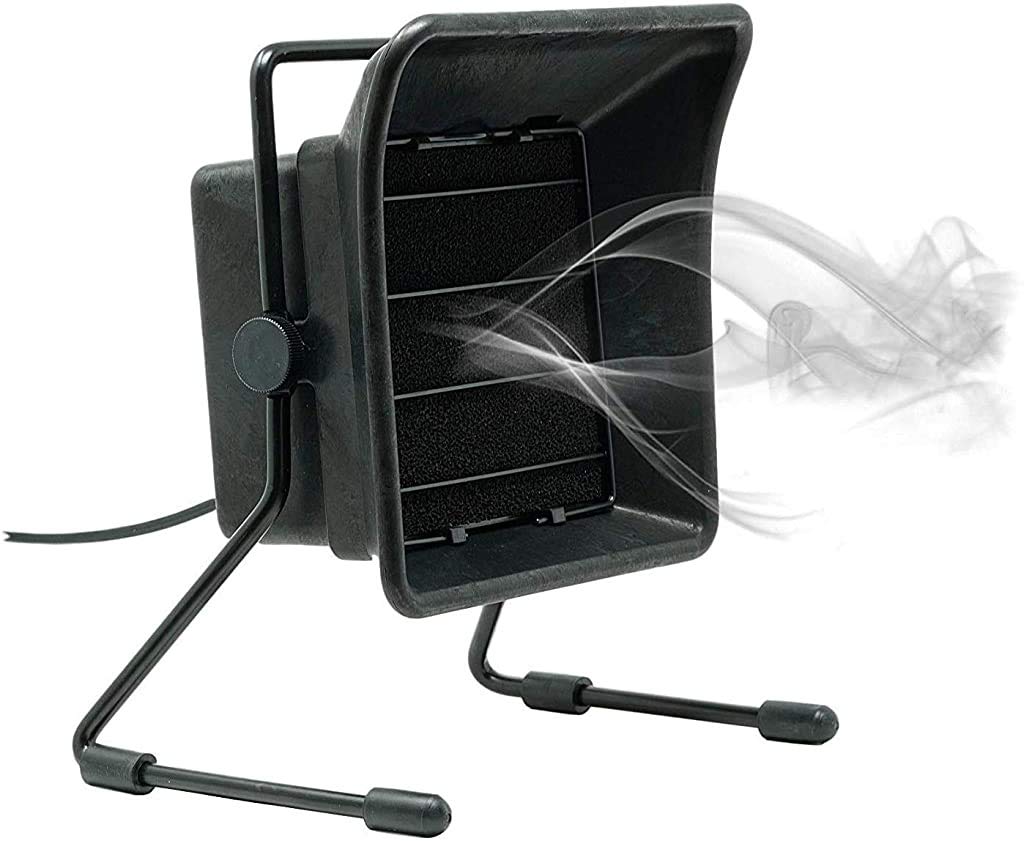
Fumes: When flux boils it gives off a little whiff of white smoke, and breathing that in for a prolonged period of time isn't super good for you. Fume extractors help with this, so we'll be giving you ones like these:
Technique
We'll be using two methods to assemble our sensor boards - one for the surface-mount components, and one for the through-hole connectors...you've already done some through-hole soldering earlier...but the surface-mount will be newer for many of you. We'll solder the surface mount parts first, then check for any visible errors, and then solder the through hole parts. In our case, the only through-hole parts we've got are the pin headers, which will melt if we hit them with hot air, so we'll be doing those last. Don't ask us how we know that.
The video below shows me throwing a couple of 0805 resistors and a (admittedly large) IC onto a random board I had sitting around and using the heatgun on it. The video is in real time. There is no audio since I didn't want you to hear me swearing. This is made using the same solder paste and gun temp specified below. Obviously your board and details will be different, but this is here just to show relative timing and acceptable levels of sloppiness. Notice how the solder, when it melts, will do so rather suddenly and in that state, the surface tension will take over, correctly orienting components. This can be quite satisfying to see happen. The satisfaction starts around ~1:35. Seriously, take a look at the video so you know what to expect!
Surface Mount Round 1
We're going to start by soldering in the passives (R's and C's) and the LED(s). These are relatively large and easy and a good starter. Since they're "dumb" components, they're much less sensitive to repeated heating/cooling cycles than some of the ICs.
First, get the parts! Mark down the values for the passives that you need from your KiCAD BOM. The passives (resistors and caps) are either laid out in the middle table in the 6.9000 parts organizer or in the reels of parts on the windowsills of EDS. Cut and take only what you need. But before you cut, use a sharpie to label the section of reel, since they all look the same after you cut them! Some things like the resistors will have codes on them to read and figure out values, but the capacitors will basically be un-figure-outable. Get the LED from the staff table.
For now, do not get the ICs or connectors!
OK the next step is to place a thin bit of solder paste on the exposed pads of those components with a syringe. We don't want this layer to be super thick; otherwise, we may short pads by applying too much solder. If you do, you can simply use a paper towel to wipe off the excess. We also have some zipties in the 6.9000 parts drawer that can be used to easily scrape solder paste off the boards. It also doesn't need to be super precise as was shown in the video.
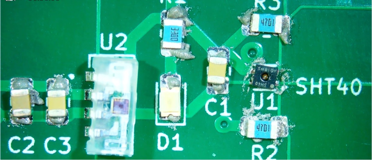
Here's my example pasting of a random student board with the relevant components. BIG CAVEAT: I WENT TOO FAR AND DID THE SOLDER PASTE FOR THE VEML AND THE SHT40 COMPONENTS. YOU SHOULD HOLD OFF ON THAT (I JUST DID IT SINCE I WAS IN A RUSH SORRY.) The passives are much, much more forgiving for figuring things out only do those for the moment!
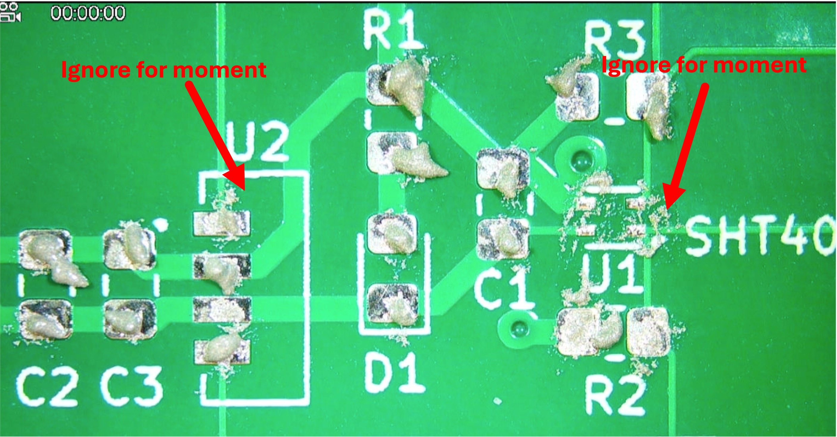
Feel free to ask the staff if you'd like a quick check on your paste job!
Place and Heat
Place the parts on the pads with tweezers. The orientation of the resistors and (non-polarized) capacitors does not matter for our board.
The LED does have an orientation (check it out on the datasheet. If you look underneath, there is a line that points toward the cathode (negative) terminal. On the frontside, there is an almost imperceptible dot for the cathode. If you get the orientation wrong, it won't work!
Again, note I just did everything at once. You should not...just do the passives, and wait until after the checkoff for the VEML and SHT40.
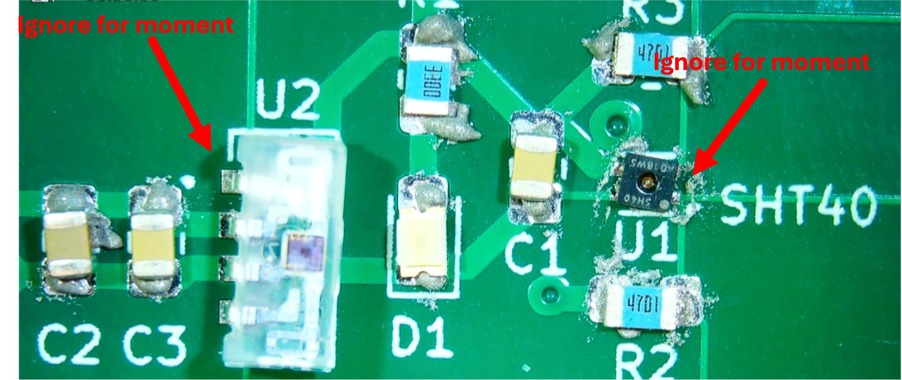
Once your parts are on the board, take it to a hot air station and let the air flow!
Using the Hot Air Station

The power switch is located at the back of the machine; turn on the station. All the LEDs should display OFF, indicating that the hot air, bed (pre-heater), and soldering iron are all turned off.
Press the red button corresponding to the bed and set the temperature to 180 C by holding on the up button. Now, using tweezers, place your board between the clamps above the pre-heating bed. Turn on the hot air gun and set its temperature to 325 C. When it reaches our desired temperature, bring the hot air over your board, and wait for the solder paste to reflow. It'll go from a dark grey paste to a chalky light grey, and then to a shiny silver liquid as shown in the earlier example video. It will nearly identical to the scene in Terminator 2: Judgement Day (specifically ~3:00 in this clip) when the T1000 starts to reliquify and reassemble in preparation for the final climactic fight sequence.
Once you get to that last step, turn off the hot air and the bed by toggling their corresponding red buttons. You will hear the automatic cool-down in the hot air gun start. While you wait for the built-in fan in the hot air gun to stop runnning, also wait for your board to cool and the solder to solidify. Once the fan stops, turn off the hot air station.
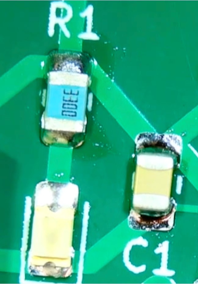
The final product should look something like this:
Desoldering
Make a mistake? Yeah you did. That's ok.
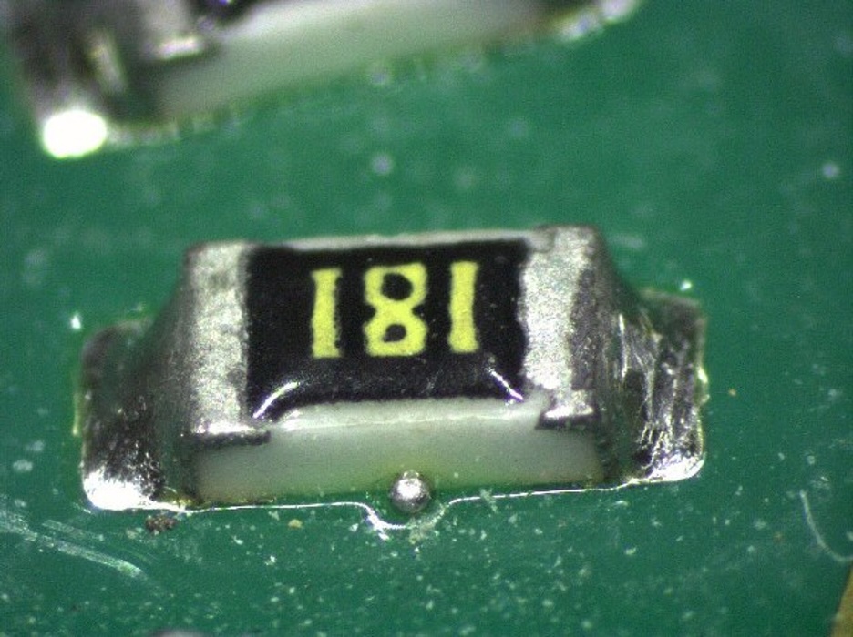
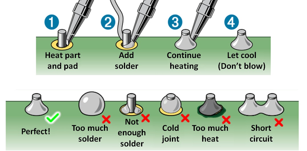
Closely examine the pads on your PCB. Make sure that all the components are soldered. Also, check to see if you have any solder bridges (left) or solder beads (right). If so, you need to desolder! What that means is that you need to remove the excess solder, because solder bridges and beads may result in a short circuit on your board (NOT GOOD).
Method 1: Solder Wick
One way to desolder is to use solder wick, which is essentially a braid of copper wire. Like in the video below, you put the solder wick on the area of solder you want to remove. Using a soldering iron, apply heat to the solder wick. Since the solder wick is made of copper, it is a good conductor and the solder in contact with it will melt, and surface tension will draw the solder into the solder wick, absorbing the solder.
Method 2: Solder Sucker
The second way to desolder is to use a solder sucker/desoldering pump. First, push down the pump. Next, in one hand, hold the soldering iron and melt the solder, and in the other hand, hold the solder sucker. Press the tip of the solder sucker to the melted solder and click the button on the solder sucker. It should then suck out the solder.
Test
Using your testpoints, apply 3V3 and GND to your board. Your LED should light up!
Checkoff: Visual Inspection
Ask a staff member to look over your assembled board.

SMT Round 2, the rest of SMT
OK, now let's add the two ICs. Paste the pads for the SHT40 and VEML7700.
Again, keeping in mind that you'll already have passives in place, take a look at the image below for my example soldering. The VEML is quite large by chip standards, so you can put on a similar amount of paste as you are for the 0805 passives. The image below is a good example. The SHT40 is a tiny chip in a rather small package. This thing needs a very tiny amount of solder on it...I put a bit down and then kinda smeared it all around like you can see below. You do not need much. Too much for this part will cause problems...so start small.

Grab a SHT40 and a VEML7700 chip from the staff table.
Place both chips on the boards.
Take a look at how I placed these two chips. Is the placement exact? No...but that's ok, surface tension will fix it for us (hopefully).
Below is a real-time (again silent) video of me flowing the board in its entirety. As a present, lucky for you, I messed up a bit (which rarely happens) and you get some bonus footage of seeing me fix the situation of when the SHT40 didn't orient correctly the time. Pay close attention, you can see I'm heavily relying on the surface tension of the solder in conjunction with gentle nudging to get the components where they need to go. I'm not making anybody do anything they don't want to do. The beauty of reflow soldering is that when done correctly, the energy-minima of the components will be exactly where you want them (due to the surface tension).
Then use the hot air station to melt the solder, same as you did for the passives. Nice. Very Nice.
Through-Hole
You'll need to solder the cable header connectors. Grab two of the 2x2 connector housings from the staff table. These are through-hole.
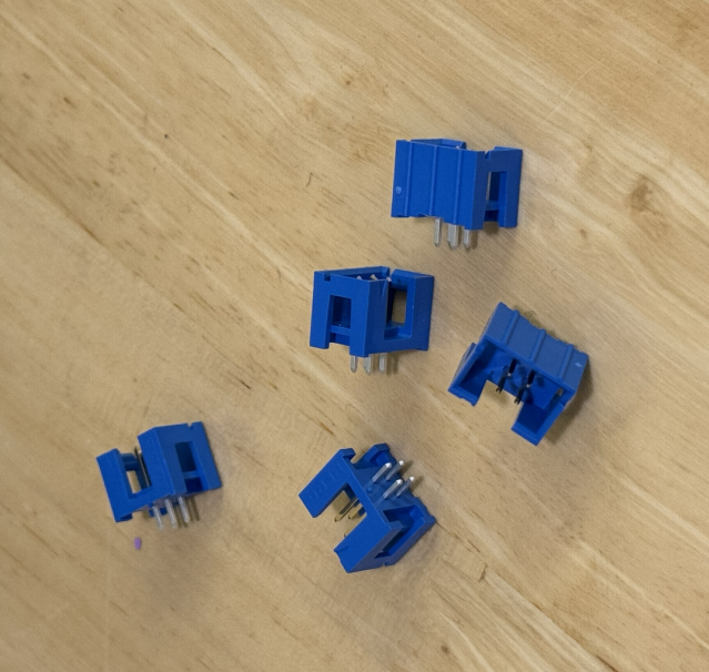
If you felt comfortable soldering through-hole during Lab01, go for it! Just make sure to use consistent orientation when inserting into your board, to avoid problems later on.
Otherwise, these videos from folks at SparkFun cover the subject fabulously! And the written guides from SparkFun and Adafruit are also quite good!
Next, solder in some through-hole testpoints. These are just little wire loops that are easy to grab onto with a scope probe if you ever need to scope that signal. We have different colors so you can use color to denote the different signals.
Connecting to our breadboard
So now, we want to connect our sensorboard to our breadboard. Let's grab some male to female jumper wires from EDS. We have male pins on our sensorboard connectors, so we will connect the female sides of our jumper wires to the connector on the PCB and plug the male sides directly into our breadboard. Use different colored jumper wires to easily differentiate between the different power and signal lines. If you are curious, there is some semblance of a color coding convention for different signal and power lines-- a quick Google search should give you some info about that.
Testing the Board!
Now let's verify that your sensor board works. There's a chance that it won't the first time and that's ok! If something seems off, we'll back up and debug with the handy test points you added in your schematic.
First, grab your ESP32 board and plug it in to your computer. The ESP32 has 3.3V and GND pins, so we'll use these to power your sensor board. Connect the jumper wires from your PCB to the appropriate ESP32 pins.
Create a second place on your breadboard to connect to the I2C jumpers and to bring the SDA and SCL lines to your pre-existing ones.
On your computer create a new PlatformIO project, and add the following lines to your platformio.ini:
build_flags =
  -DARDUINO_USB_MODE
  -DARDUINO_USB_CDC_ON_BOOT

lib_deps =
  sparkfun/SparkFun VEML7700 Arduino Library@1.0.0
  adafruit/Adafruit SHT4x Library @ ^1.0.5
  SPI
Basically we're going to use Sparkfun's VEML library and Adafruit's SHT4x library. Here the code to put into your main.cpp. Make sure you understand what's happening!
#include <Arduino.h>
#include <SparkFun_VEML7700_Arduino_Library.h> // Click here to get the library: http://librarymanager/All#SparkFun_VEML7700
#include "Adafruit_SHT4x.h"

VEML7700 mySensor; // Create a VEML7700 object
Adafruit_SHT4x sht4 = Adafruit_SHT4x();

#define I2C_SDA 4
#define I2C_SCL 5

int getting_period = 500;
float THRESHOLD = 1000.0;
uint32_t last_time=0; //used for timing

void setup() {
  Serial.begin(115200);
  delay(2000); // delay so terminal connects and catches up
  Serial.println(F("SparkFun VEML7700 Example"));

  Wire.begin(I2C_SDA, I2C_SCL);

  // mySensor.enableDebugging(); // Uncomment this line to enable helpful debug messages on Serial

  if (! mySensor.begin()) {
    Serial.println("Couldn't find VEML7700");
    while (1) delay (1);
  }
  Serial.println("Found VEML7700");


  if (! sht4.begin()) {
    Serial.println("Couldn't find SHT4x");
    while (1) delay(1);
  }
  sht4.setPrecision(SHT4X_HIGH_PRECISION);
  sht4.setHeater(SHT4X_NO_HEATER);
  Serial.println("Found SHT4x sensor");
}

void loop() {
  sensors_event_t humidity, temp;
  float lux = mySensor.getLux();

  if (lux >= THRESHOLD) {
    getting_period = 500;
  }
    else {
    getting_period = 3000;
  }

  if ((millis() - last_time) > getting_period) {
    Serial.print("Lux: "); Serial.println(lux);
    sht4.getEvent(&humidity, &temp);// populate temp and humidity objects with fresh data
    Serial.print("Temperature: "); Serial.print(temp.temperature); Serial.println(" degrees C");
    Serial.print("Humidity: "); Serial.print(humidity.relative_humidity); Serial.println("% rH");
    last_time = millis(); //  reset timer
  }
  delay(100);
}
Compile and upload the code. Turn on the serial monitor and if all is good you should have readings.
When you get things working, find a staff member and allow them to join you in celebration of your first working PCB! Please explain to them what the code is doing.