Lab 6
Please Log In for full access to the web site.
Note that this link will take you to an external site (https://shimmer.mit.edu) to authenticate, and then you will be redirected back to this page.
Learning Objectives
Today's lab will focus on assembling and testing your buck coverter boards. We'll:
- Solder the surface mount parts.
- Solder through-hole parts.
- Test your boards!
- Get a checkoff.
Buck converter assembly
This is now the second board that you designed and made. We'll approach the assembly much like we did for the sensor boards, just with different components.
However, since we're kinda pro at this now, we'll simplify the instructors. Feel free to refer to lab05 where you want more detail.
Surface Mount
We're going to start by soldering in the SMT parts.
-
Apply solder paste to all the pads for the SMD parts: Resistors, Capacitors, Inductor, LEDs, and the LM3971 IC pads.
-
Get all your parts. R's and C's from the EDS main room, the rest from the staff table. The 4.7uF caps are in the drawer on the staff table.
-
Place the components on the pads, and then use the hot air to melt the solder. Should be the same as last week. Use the same temperatures as last week.
-
Using your testpoint pads, test your LED (or LEDs) by applying power to those sub-circuits.
Thru-hole
Get the (blue) connectors and the testpoints and solder those in.
Checkoff: Visual Inspection
Ask a staff member to look over your assembled board.

Cable Connections
We will be using ribbon cables to connect our power board, sensor board, and our breadboard, so let's make some cables! Specifically, we will make three 4-conductor ribbon cables using IDC (insulation displacement contact) connectors.
One cable should go from the power board output power connector to the sensor board power connector. Hopefully you oriented your headers and connectors correctly so that the correct signals make there way from here to there!
Another cable will go from the power board input power connector to the bq25185 breakout. Here we want to get the output from bq25185 chip on that board, which we can access via the green terminal block, specifically the "4.5 V" and "-" (aka ground) terminals...alternatively you can use VU and GND on the connector pins. Strip the appropriate wires from your cable and make the connections.
Making Our Own Cables!
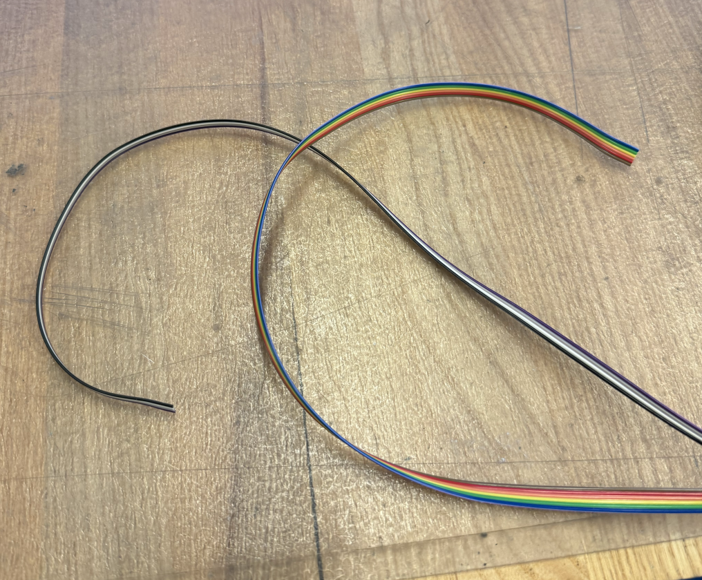
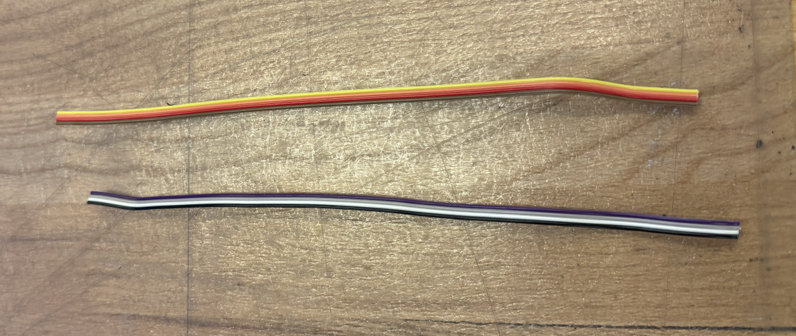
First, peel off 4 conductors from a ribbon cable. You can use the gray ribbon cable or the multicolored one. I like to use one set of colors for the I2C cable and another set for the power cables, but that's just me.
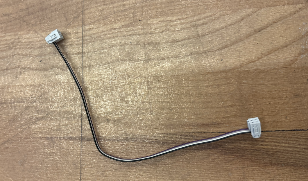
Make four ~12" (~25-30 cm) cables. Here's a picture of two:
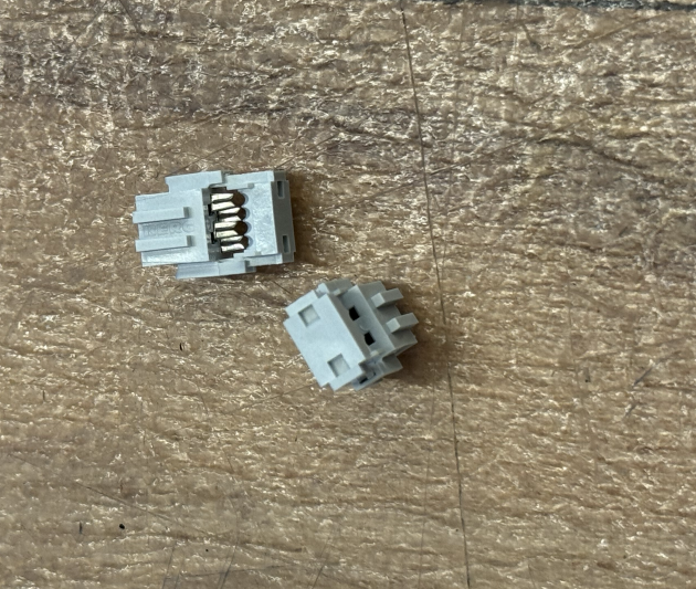
Grab seven yes, seven 4-pin IDC connectors.
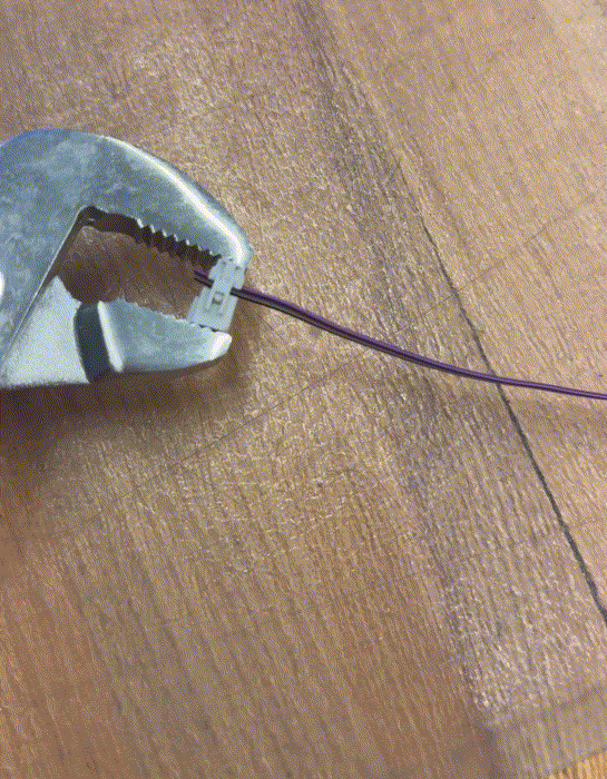
Insert the cable into the opening of the connector, past the end, and keep it straight. Then clamp down to make the contact. I like to use a set of pliers to do it. It's very satisfying.
IMPORTANT For each cable, you MUST check the orientation of the connectors on both the baords it is connecting to. Check which pin corresponds with which signal on each of the two boards and check how each wire maps between the two boards. Orient the second side of your cable into its connector based on this mapping. Remember, the orientation of your connector itself is determined by how you have soldered the connector header into your board. You can either desolder and reorient your connector header on your board or twist your cable in between the two connectors as needed. If your pin mapping is different between the two boards and you cannot figure out the mapping, ask a staff member for help!
Now do the same for the other connectors. You will end up with three complete cables and a fourth cable with a single connector. When you're finished, each cable will look like so:
If you want to be pro, use a diagonal cutter to cut the overhanging cable bit flush with the connector.
Testing Our Cables!
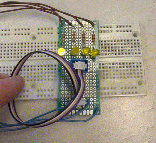
We built a little board for testing your cables connections. Simply, plug your MTA cable(s) into the connectors on this test board. If your cable is made correctly, the LEDs in series with your cable connections should light up!
Connecting to our breadboard
OK, so now we have a bit of a problem for our final two cables. One of these cables goes from the power board output connector to your breadboard power rails to power your breadboard. The other goes from the sensor board I2C connector to the breadboard.
But to connect to your breadboard we have a bit of an issue, in that the 2x2 pin arrangement isn't really compatible with breadboards, because any two vertical pins will be shorted together.
For the power connector this is ok, as you only have +3V3 and ground, so you just need to make sure they are oriented appropriately with the power rails on your breadboard.
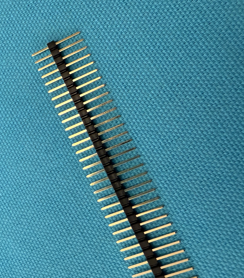
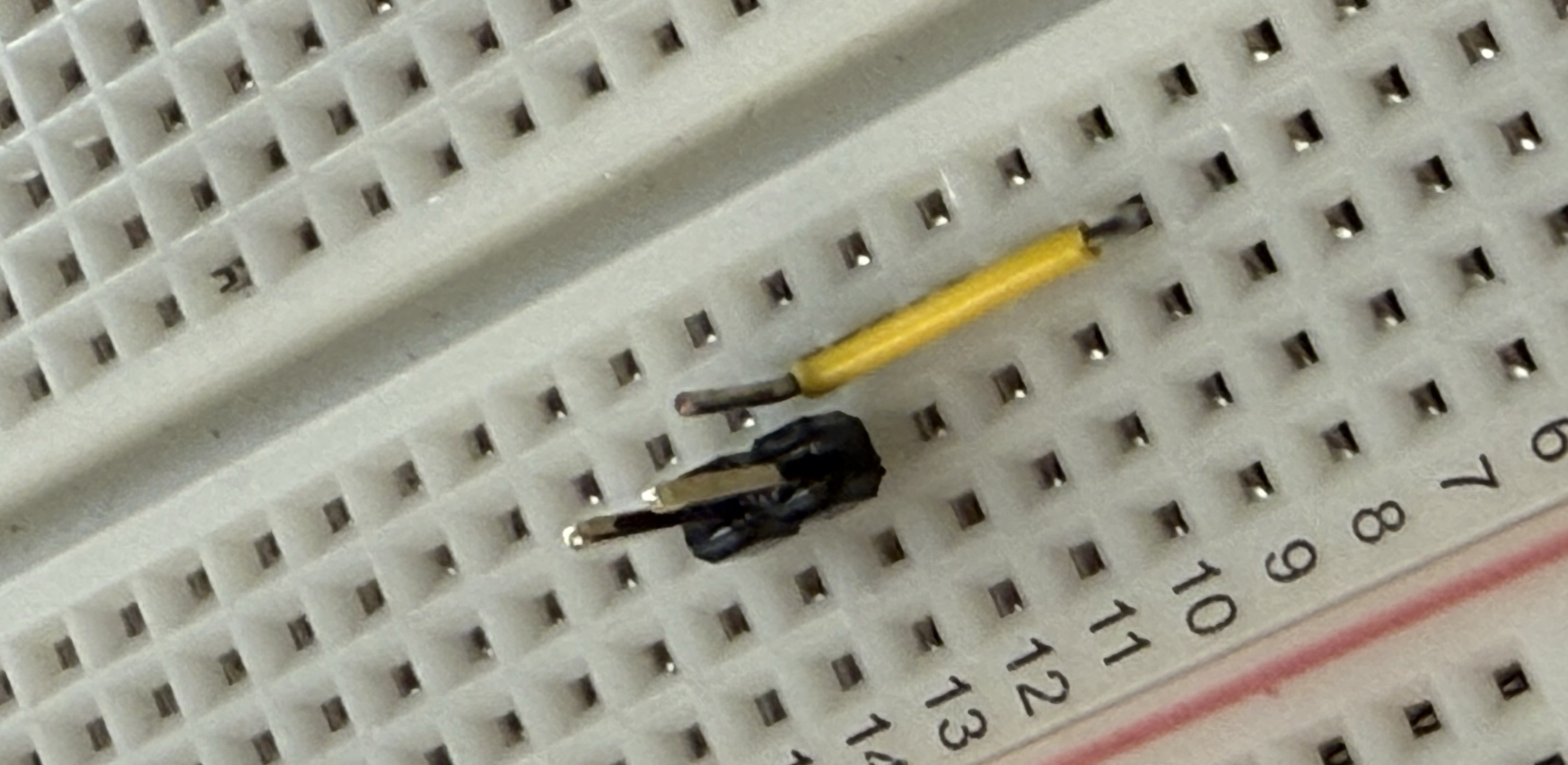
Get a long male header (also in the organizer on the staff table)-- it's a bit different than the ones we're used to, and looks like so. The "short" end of this one will still go into the breadboard long enough to make good contact.
Insert into the breadboard.

And then attach the power cable. Just be careful not to short power and ground together! Make sure they are oriented horizontally, not vertically.
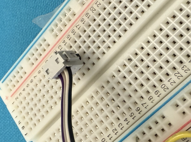
For the I2C connector, we're going to have a bit of a workaround. Get another 2-pin long male header, and insert into the breadboard. Now, wherever your third signal is, use a short jumper wire to bring that to a separate vertical row, like so:
Now when you attach your cable, each of the 3 signals will be in distinct columns of the breadboard, like so:

Testing the Board(s)!
Now let's verify that your buckboard + sensorboard combo works. There's a chance that they won't work immediately and that's ok! If something seems off, we'll back up and debug with the handy test points and/or our friends the oscilloscope and multimeter.
First, configure your ESP32 and bq25185 on the breadboard. The ESP32 should share GND with the bq25185, but now instead of powering 3V3 with the buck on the bq25185, we'll be powering it with the 3V3 supplied to the breadboard from your buckboard PCB via the ribbon cable. So, that means the 3V connector on the bq25185 should NOT be connected to anything. You don't want two bucks competing to set the same voltage rail. D+ and D- should still be connected between the two, as that is how your computer will talk to the ESP32 over serial (of the USB-CDC variety). Then, plug your ESP32 board in to your computer.
As described earlier, your buckboard input should be connected to the output of the green terminal of the bq25185 (4.5V and GND), and one output should be connected to the 3V3 rail of each of the sensorboard and breadboard.
Now connect the data lines between your breadboard and the sensorboard (similar to last week but now with fancy cables!). Connect to the I2C port on the sensorboard with one end of the cable, and to the GPIO pins on the ESP32 through the work-around from above.
On your computer create a new PlatformIO project, and add the following lines
to your platformio.ini:
build_flags =
  -DARDUINO_USB_MODE
  -DARDUINO_USB_CDC_ON_BOOT

lib_deps =
  sparkfun/SparkFun VEML7700 Arduino Library@1.0.0
  adafruit/Adafruit SHT4x Library @ ^1.0.5
  SPI
We're still using Sparkfun's VEML library and Adafruit's SHT4x library, but we
will add some WiFi usage to test our power delivery!
Here the code to put into your main.cpp.
Make sure you understand what's happening!
#include <Arduino.h>
#include <SparkFun_VEML7700_Arduino_Library.h> // Click here to get the library: http://librarymanager/All#SparkFun_VEML7700
#include "Adafruit_SHT4x.h"
#include <WiFi.h>
#include <string.h>

VEML7700 veml;
Adafruit_SHT4x sht4 = Adafruit_SHT4x();

#define I2C_SDA 4
#define I2C_SCL 5

int getting_period = 500;
float THRESHOLD = 1000.0;
uint32_t last_time = 0; //used for timing

void do_http_GET(char* host, char* request, char* response, uint16_t response_size, uint16_t response_timeout, uint8_t serial);
uint8_t char_append(char* buff, char c, uint16_t buff_size);

const int RESPONSE_TIMEOUT = 30000; //ms to wait for response from host
const int GETTING_PERIOD = 5000; //periodicity of getting a number fact.
const uint16_t IN_BUFFER_SIZE = 1000; //size of buffer to hold HTTP request
const uint16_t OUT_BUFFER_SIZE = 1000; //size of buffer to hold HTTP response
char request_buffer[IN_BUFFER_SIZE]; //char array buffer to hold HTTP request
char response_buffer[OUT_BUFFER_SIZE]; //char array buffer to hold HTTP response

char network[] = "EECS_Labs";
char password[] = "";

void test_message(){
  WiFi.begin(network, password);
  //if using channel/mac specification for crowded bands use the following:
  //WiFi.begin(network, password, channel, bssid);
  uint8_t count = 0; //count used for Wifi check times
  Serial.print("Attempting to connect to ");
  Serial.println(network);
  while (WiFi.status() != WL_CONNECTED && count < 6) { //can change this to more attempts
    delay(500);
    Serial.print(".");
    count++;
  }
  //delay(2000);  //acceptable since it is in the setup function.
  if (WiFi.isConnected()) { //if we connected then print our IP, Mac, and SSID we're on
    Serial.println("CONNECTED!");
    delay(500);
    //formulate GET request...first line:
    sprintf(request_buffer, "GET http://numbersapi.com/%d/trivia HTTP/1.1\r\n", random(200));
    strcat(request_buffer, "Host: numbersapi.com\r\n"); //add more to the end
    strcat(request_buffer, "\r\n"); //add blank line!
    //submit to function that performs GET.  It will return output using response_buffer char array
    do_http_GET("numbersapi.com", request_buffer, response_buffer, OUT_BUFFER_SIZE, RESPONSE_TIMEOUT, true);
  } else { //if we failed to connect just Try again.
    Serial.println("Failed to Connect :/  Will try next time.");
    Serial.println(WiFi.status());
    //ESP.restart(); // restart the ESP (proper way)
  }
  WiFi.disconnect();
}

void setup() {
  Serial.begin(115200);
  Serial.println(F("Booting up!"));

  Wire.begin(I2C_SDA, I2C_SCL);

  // veml.enableDebugging(); // Uncomment this line to enable helpful debug messages on Serial

  if (!veml.begin()) {
    Serial.println("Couldn't find VEML7700");
    while (1) delay(1);
  }
  Serial.println("Found VEML7700");

  if (!sht4.begin()) {
    Serial.println("Couldn't find SHT4x");
    while (1) delay(1);
  }
  sht4.setPrecision(SHT4X_HIGH_PRECISION);
  sht4.setHeater(SHT4X_NO_HEATER);
  Serial.println("Found SHT4x sensor");
}

void loop() {
  sensors_event_t humidity, temp;
  float lux = veml.getLux();

  if (lux >= THRESHOLD) {
    getting_period = 500;
  } else {
    getting_period = 3000;
  }

  if ((millis() - last_time) > getting_period) {
    Serial.print("Lux: "); Serial.println(lux);
    sht4.getEvent(&humidity, &temp);// populate temp and humidity objects with fresh data
    Serial.print("Temperature: "); Serial.print(temp.temperature); Serial.println(" degrees C");
    Serial.print("Humidity: "); Serial.print(humidity.relative_humidity); Serial.println("% rH");
    test_message();
    last_time = millis(); // reset timer
  }
  delay(100);
}

/*----------------------------------
   char_append Function:
   Arguments:
      char* buff: pointer to character array which we will append a
      char c:
      uint16_t buff_size: size of buffer buff

   Return value:
      boolean: True if character appended, False if not appended (indicating buffer full)
*/
uint8_t char_append(char* buff, char c, uint16_t buff_size) {
  int len = strlen(buff);
  if (len > buff_size) return false;
  buff[len] = c;
  buff[len + 1] = '\0';
  return true;
}

/*----------------------------------
   do_http_GET Function:
   Arguments:
      char* host: null-terminated char-array containing host to connect to
      char* request: null-terminated char-arry containing properly formatted HTTP GET request
      char* response: char-array used as output for function to contain response
      uint16_t response_size: size of response buffer (in bytes)
      uint16_t response_timeout: duration we'll wait (in ms) for a response from server
      uint8_t serial: used for printing debug information to terminal (true prints, false doesn't)
   Return value:
      void (none)
*/
void do_http_GET(char* host, char* request, char* response, uint16_t response_size, uint16_t response_timeout, uint8_t serial) {
  WiFiClient client; //instantiate a client object
  if (client.connect(host, 80)) { //try to connect to host on port 80
    if (serial) Serial.print(request);//Can do one-line if statements in C without curly braces
    client.print(request);
    memset(response, 0, response_size); //Null out (0 is the value of the null terminator '\0') entire buffer
    uint32_t count = millis();
    while (client.connected()) { //while we remain connected read out data coming back
      client.readBytesUntil('\n', response, response_size);
      if (serial) Serial.println(response);
      if (strcmp(response, "\r") == 0) { //found a blank line! (end of response header)
        break;
      }
      memset(response, 0, response_size);
      if (millis() - count > response_timeout) break;
    }
    memset(response, 0, response_size);  //empty in prep to store body
    count = millis();
    while (client.available()) { //read out remaining text (body of response)
      char_append(response, client.read(), OUT_BUFFER_SIZE);
    }
    if (serial) Serial.println(response);
    client.stop();
    if (serial) Serial.println("-----------");
  } else {
    if (serial) Serial.println("connection failed :/");
    if (serial) Serial.println("wait 0.5 sec...");
    client.stop();
  }
}
Compile and upload the code. Turn on the serial monitor, and if all is good, you should have sensor readings and periodic HTTP requests.
Take a look at the 3V3 coming out of the buckboard (hmm... where would one look to test a signal?) on an oscilloscope or a Joulescope. Your output may have some blips when load changes, but it should be pretty stable!
When you get things working, find a staff member and allow them to join you in celebration of your first working PCB! Please explain to them what the code is doing.