Lab 6
Please Log In for full access to the web site.
Note that this link will take you to an external site (https://shimmer.mit.edu) to authenticate, and then you will be redirected back to this page.
Learning Objectives
Today's lab has two goals - assembling your sensor boards, and then going over your Sentimet milestones and deliverables for this week. As a result, we'll:
- Solder surface mount parts.
- Have staff inspect your board, get a checkoff.
- Solder through-hole parts.
- Test your boards!
- Meet with staff as a team to go thru milestone chart. This is in preparation for next week's review02.
Plugin Installation
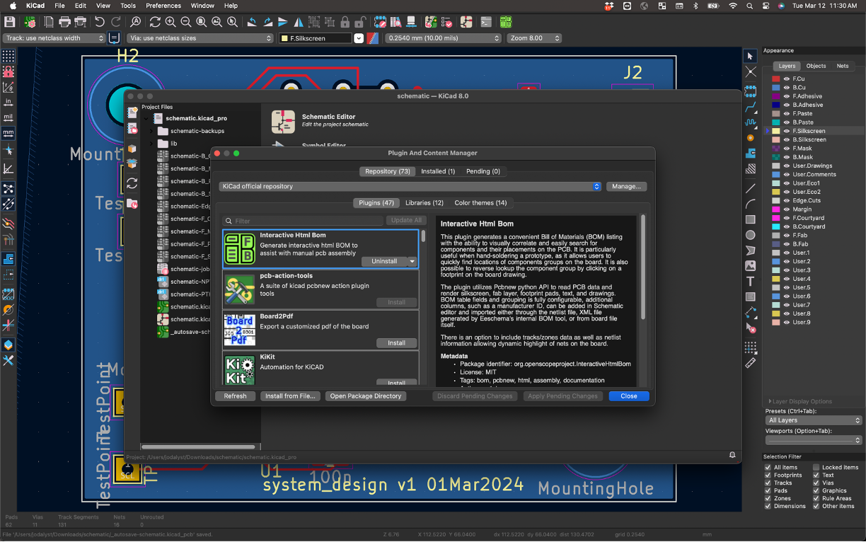
KiCad has a really neat plugin that can be activated which provides an easy-to-read "GUI" of your board and its components and elements. It can be very helpful in the assembly that you'll be doing. To install, first go into your main KiCad page and Tools>Plugin and Content Manager

In there, look for the Interactive HTML BOM plugin. Install it.
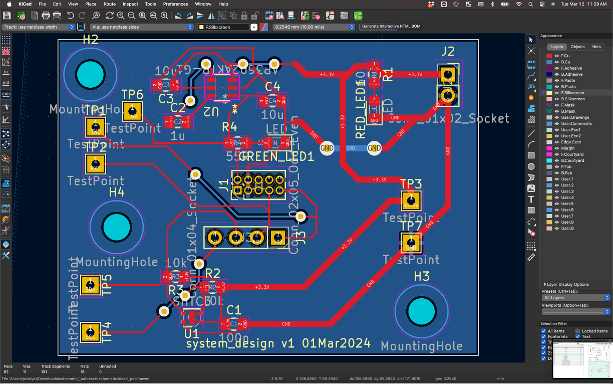
Once installed open up your PCB that you want to use with the plugin. In the top panel there should now be a bright-green button you can push corresponding to this plugin. Click it.
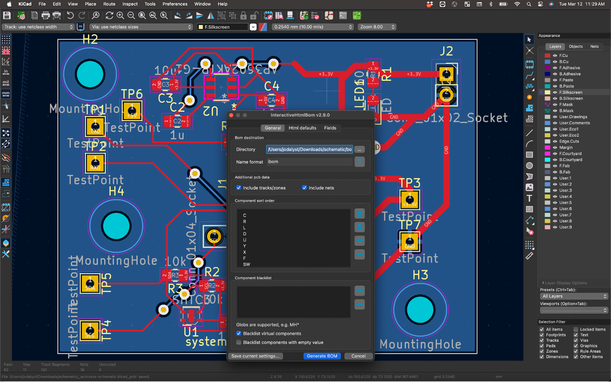
In the window that comes up, make sure to check the options about including nets and traces. When ready, then go and click Generate BOM.
You should be transferred to your web browser (hopefully it doesn't block this) and it'll present you with a web page that is your board along with all your components. There's different features you can look at including parts that need to be assembled:
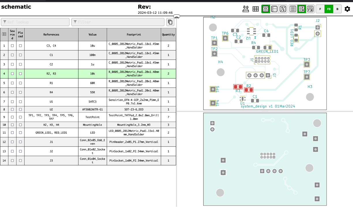
as well as your traces and other angles of your board.
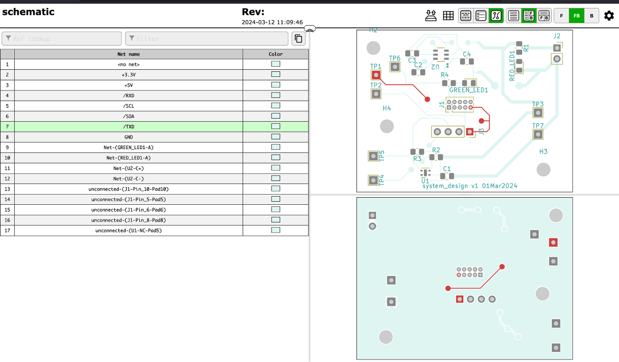
This tool can be really help when assembling since it will tell you what parts go where in a very easy-to-read and visualize manner.
Sensor board assembly
We have our sensor & power boards back! This is very cool -- these are designs you made and you laid out. Right now we just have the boards themselves, and we'll need to solder components onto them to make them functional circuits. Most of our components are surface mount, so we'll need to use different methods than we'd use for through-hole soldering, which you might have done before, like in 6.200.
We'll show ya the technique, but first, a note on safety:
Safety
There's a few hazards in soldering:
- Hot Stuff: The soldering iron is really hot, like moreso than Donna Summer's 1979 single. Leaded solder melts at around 370°F give or take depending on what alloy you get, and lead-free melts at around 420°F. As a result the soldering iron has to be at least that temperature, so be careful to not burn yourself! If you drop the iron just let it fall and get out of the way, resist the urge to catch it.
Also be sure to wear safety glasses - I've got friends of friends who've gotten hot beads of solder flicked into their eyes because they were soldering wires under tension. They're blind now. Wear safety glasses.
- Heavy Metals: Traditionally solder is a mix of lead and tin, but since lead's toxic, manufactured goods are required to use lead-free solder instead. The leaded stuff flows a little better and is easier to work with, so it's what we'll use in lab. Lead's super toxic once it gets in your bloodstream, so be super sure to wash your hands after soldering! You don't want to ingest any tiny solder bits. Lead is also pretty soft so you don't have to worry much about stabbing yourself with it and getting some in your blood that way, but just be careful. Holding it in your hands is totally okay though, you don't need gloves or anything as long as you wash 'em afterwards.
-
Solder Paste: We'll be using solder paste today to solder our tiny surface mount components. It's super cool and easy to use, but comes with some extra lead exposure potential. Compared to a spool of solder wire, solder paste is a lot harder to wash off your hands since it can easily work its way into the nooks and crannies of your fingerprints, so we're going to ask that you wear gloves while handling solder paste.
-
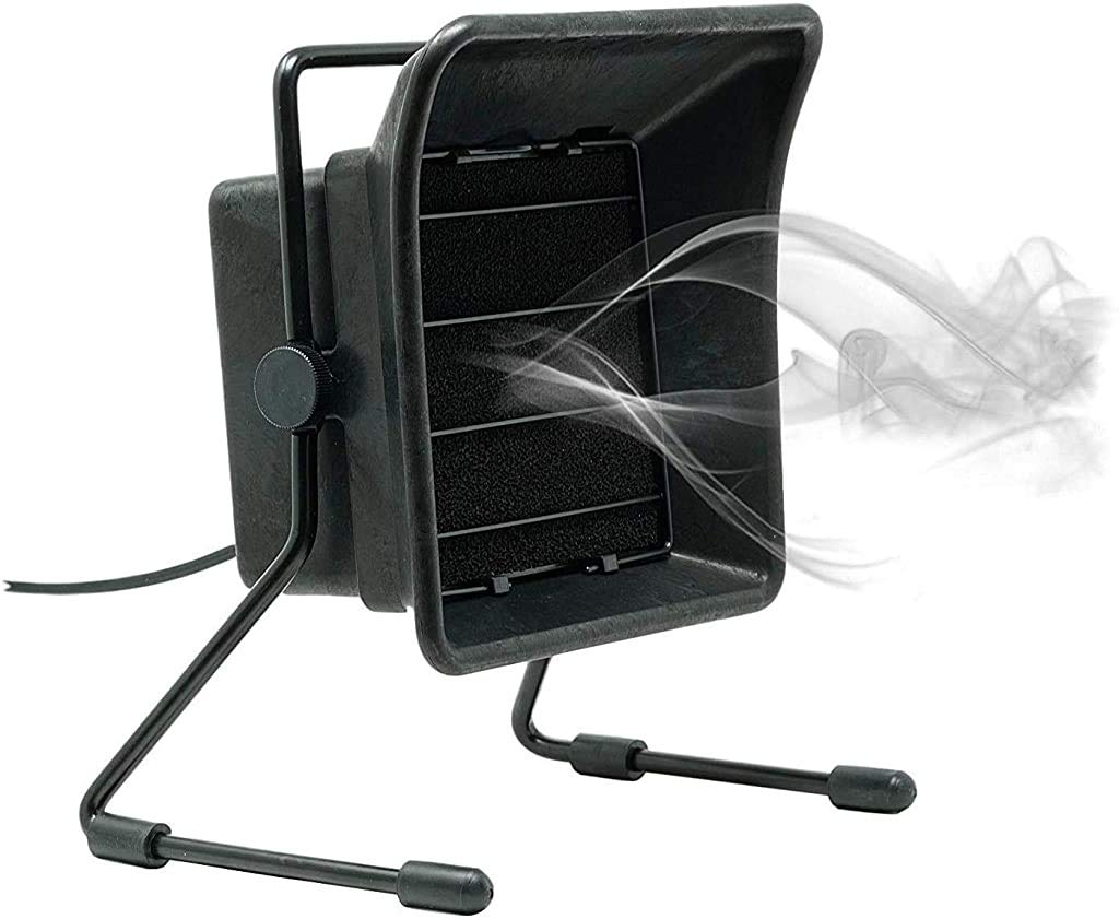
Fumes: When flux boils it gives off a little whiff of white smoke, and breathing that in for a prolonged period of time isn't super good for you. Fume extractors help with this, so we'll be giving you ones like these:
Technique
We'll be using two methods to assemble our sensor boards - one for the surface-mount components, and one for the through-hole connectors. We'll solder the surface mount parts first, then check for any visible errors, and then solder the through hole parts. In our case, the only through-hole parts we've got are the pin headers, which will melt if we hit them with hot air, so we'll be doing those last. Don't ask us how we know that.
We hope that soldering takes no more than an hour of the lab session. If you are struggling, please ask for help!
Surface Mount Overview
We'll do surface mount by placing a thin bit of solder paste on the exposed pads of the board with a syringe. We don't want this layer to be super thick; otherwise, we may short pads by applying too much solder. If you do, you can simply use a paper towel to wipe off the excess. It also doesn't need to be super precise! Here's about what we're looking for:
Here is another example of what we are looking for! Remember: not too thick nor precise layers of solder! Unlike this video though, we will be placing the solder paste on all the exposed solder pads before applying heat to the board.
Feel free to ask the staff if you'd like a quick check on your paste job!
Get parts
Once you've got your pasted board, time to get parts! Mark down the values for the passives that you need from your KiCAD BOM. The passives (resistors and caps) are by the window in reels.
Find the reel with the value you need. Cut off a bit. But before you cut, use a sharpie to label the section of reel, since they all look the same after you cut them!
Get the ICs and LEDs from the staff table, along with connectors, and any other doodads.
Place and heat
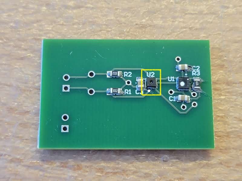
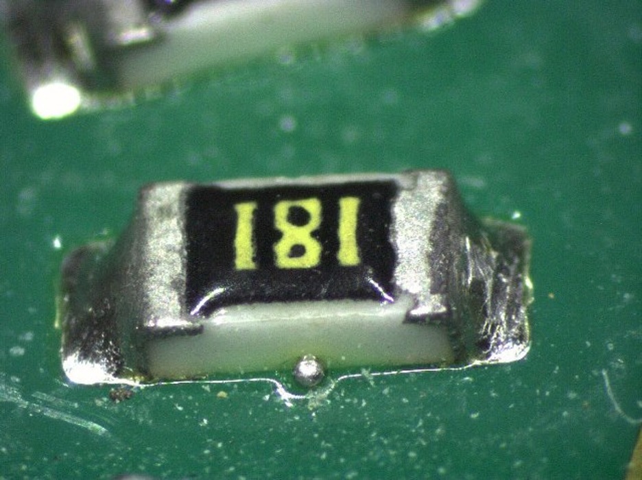
Place the parts on the pads with tweezers. The orientation of the resistors and (non-polarized) capacitors does not matter for our board. Be sure to pay attention to the orientation marker on the sensors - the dot on the chip should line up with the dot on the silkscreen. Here's what that looks like:
Once your parts are on the board, take it to a hot air station.
Using the Hot Air Station
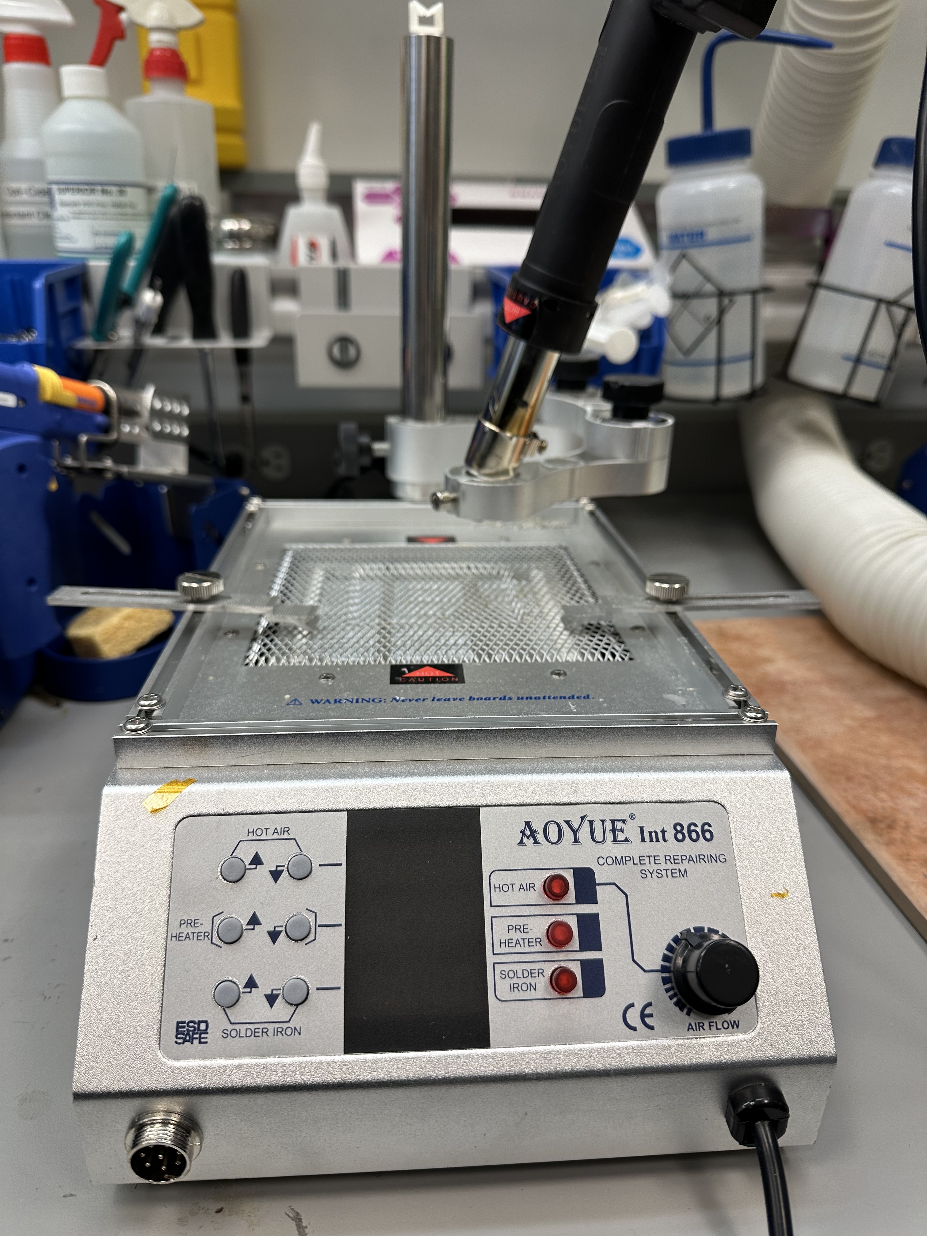
The power switch is located at the back of the machine; turn on the station. All the LEDs should display OFF, indicating that the hot air, bed (pre-heater), and soldering iron are all turned off.
Press the red button corresponding to the bed and set the temperature to 400 by holding on the up button. Now, using tweezers, place your board between the clamps above the pre-heating bed. Turn on the hot air gun and set its temperature to 450. When it reaches our desired temperature, bring the hot air over your board, and wait for the solder paste to reflow. It'll go from a dark grey paste to a chalky light grey, and then to a shiny silver liquid.
Once you get to that last step, turn off the hot air and the bed by toggling their corresponding red buttons. You will hear the automatic cool-down in the hot air gun start. While you wait for the built-in fan in the hot air gun to stop runnning, also wait for your board to cool and the solder to solidify. Once the fan stops, turn off the hot air station.
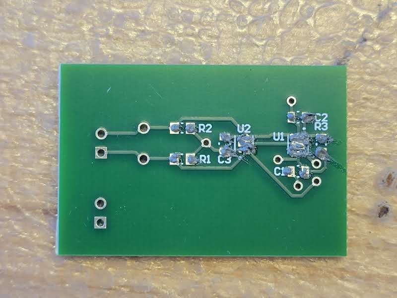
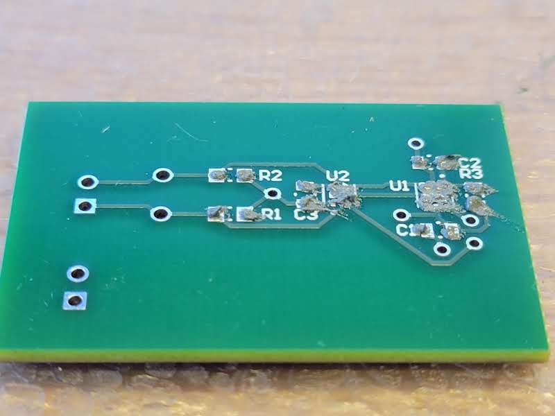
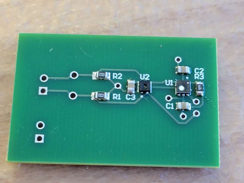
The final product should look something like this:
Desoldering
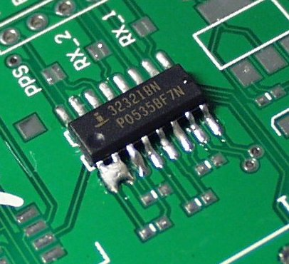
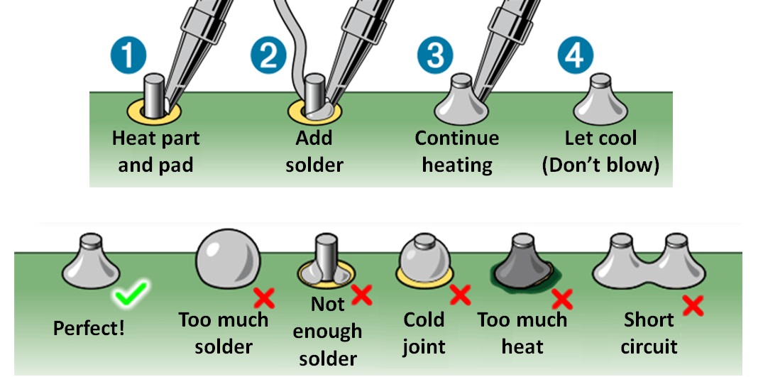
Closely examine the pads on your PCB. Make sure that all the components are soldered. Also, check to see if you have any solder bridges (left) or solder beads (right). If so, you need to desolder! What that means is that you need to remove the excess solder, because solder bridges and beads may result in a short circuit on your board (NOT GOOD).
Method 1: Solder Wick
One way to desolder is to use solder wick, which is essentially a braid of copper wire. Like in the video below, you put the solder wick on the area of solder you want to remove. Using a soldering iron, apply heat to the solder wick. Since the solder wick is made of copper, it is a good conductor and the solder in contact with it will melt, resulting in the solder wick absorbing the solder.
Method 2: Solder Sucker
The second way to desolder is to use a solder sucker/desoldering pump. First, push down the pump. Next, in one hand, hold the soldering iron and melt the solder, and in the other hand, hold the solder sucker. Press the tip of the solder sucker to the melted solder and click the button on the solder sucker. It should then suck out the solder.
Checkoff: Visual Inspection
Ask a staff member to look over your assembled board.

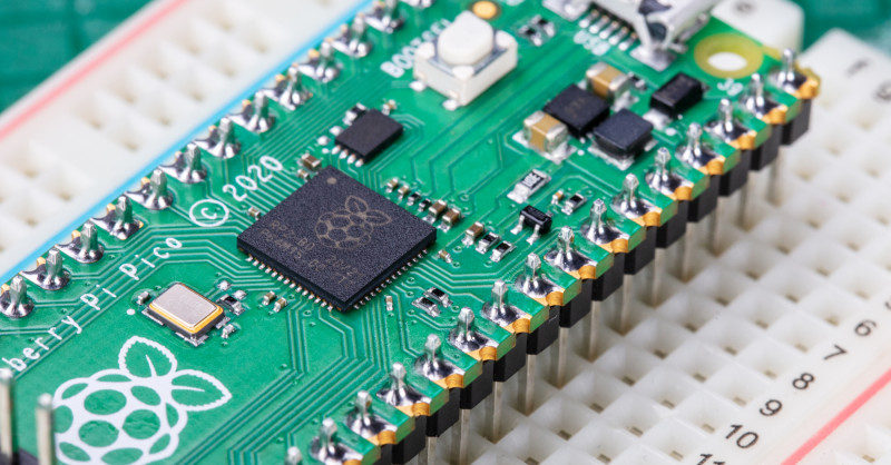
Through-Hole
You'll need to solder the pin header connectors. These are through-hole, like those of the SHTC3 breakout board. If you felt comfortable soldering through-hole during Lab01, go for it! Otherwise, these videos from my friends at SparkFun cover the subject fabulously! And the written guides from SparkFun and Adafruit are also quite good!
Instead of using the helping hands like they did in these videos, you can use a breadboard for soldering the connectors. Push the long end of the pin headers into a row in the breadboard, and then put the through-holes through the pins. Make sure the plastic is fully flushed against the board before soldering.
You can optionally solder the through-hole testpoints. Those are just little wire loops that are easy to grab onto with a scope probe if you ever need to scope that signal.
Making Our Own Cables!
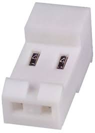
We will be using MTA cables to connect our sensor board to our ESP32, so let's make some! Specifically, we will make 2 MTA cables: one with 2 wires, one with 4 wires.
First, get some solid core wires from the spools outside of EDS, because sadly we cannot use jumper wires for these cables. Als, grab a 2-pin and a 4-pin MTA connector.
Following the video below, use the insertion tool to push a wire into each slot of the MTA connector. For the power cable, you may want to use a red and a black wire for 3.3V and GND, respectively.
Finally, wire-strip the other end of the wires. And now, you have your MTA cables!
Testing Our Cables!
We built a PCB board for testing your MTA Cable connections. Simply, plug your MTA cable(s) into the connectors on this test board. If your cable is made correctly, the LEDs in series with your cable connections should light up!
If it doesn't light up, push the cable down a bit more with the MTA-100 tool and test again.
Testing the Board!
Now let's verify that your sensor board works. There's a good chance that it won't the first time and that's ok! If something seems off, we'll backup and debug with the handy test points you added in your schematic.
First, grab your ESP32 board and plug it in to your computer. The ESP32 has 3.3V and GND pins, so we'll use these for now to power your sensor board. Using your 2-pin MTA cable, plug in your sensor board power to your ESP. The first sign of success is that your power indicator LED should turn on. If it doesn't, check your solder connections visually and with a multimeter.
We've set up a test station in lab where you can plug in your sensorboard to an ESP to test that it's working. Below is the code running on the ESP that tests the sensors. Before plugging in your sensorboard, unplug the ESP from the computer to unpower it.
#include <Arduino.h>
#include <HardwareSerial.h>
#include "SparkFun_SHTC3.h"

HardwareSerial pmsSerial(1); // Use the second hardware serial port of ESP32

SHTC3 mySHTC3; // Declare an instance of the SHTC3 class

#define I2C_SDA 2
#define I2C_SCL 3

bool shtc_good = false;

void errorDecoder(SHTC3_Status_TypeDef message, bool *success_flag) // The errorDecoder function prints "SHTC3_Status_TypeDef" resultsin a human-friendly way
{
  switch (message)
  {
  case SHTC3_Status_Nominal:
    Serial.println("SHTC3 Nominal");
    *success_flag = true;
    break;
  case SHTC3_Status_Error:
    Serial.println("SHTC3 Error");
    *success_flag = false;
    break;
  case SHTC3_Status_CRC_Fail:
    Serial.println("SHTC3 CRC Fail");
    *success_flag = false;
    break;
  default:
    Serial.println("Unknown SHTC3 return code");
    *success_flag = false;
    break;
  }
}

void setup()
{
  Serial.begin(115200);
  delay(1000);
  Serial.println("lets see if our sensors work");

  Serial.println("initializing PMS serial");
  pmsSerial.begin(9600, SERIAL_8N1, 9, 8); // Start hardware serial with PMS7003 at 9600 baud rate, RX pin is 9, TX pin is 8
  Serial.println("done initializing PMS serial");

  Serial.println("initializing SHTC3 I2C");
  Wire.begin(I2C_SDA, I2C_SCL);
  errorDecoder(mySHTC3.begin(), &shtc_good);
  Serial.println("done initializing SHTC3 I2C");

}

void loop()
{
  delay(1000);
  if (shtc_good)
  {
    mySHTC3.update();

    float temperature = mySHTC3.toDegF();
    float humidity = mySHTC3.toPercent();

    Serial.printf("T: %0.2fF\nH: %0.2f%%\n", temperature, humidity);
  }
  else
  {
    Serial.println("no good SHTC3");
    errorDecoder(mySHTC3.begin(), &shtc_good);
  }
  if (pmsSerial.available())
  { // Check if there is data available from the PMS7003
    // Look for the start character
    if (pmsSerial.peek() == 0x42)
    { // Peek at the incoming byte to check for the start character without removing it from the buffer
      uint8_t buffer[32];
      if (pmsSerial.available() >= 32)
      { // Check if at least 32 bytes are available to read
        for (int i = 0; i < 32; i++)
        {
          buffer[i] = pmsSerial.read(); // Read a byte from the serial port and store it in the buffer
        }

        // Check frame header 0x42 0x4D
        if (buffer[0] == 0x42 && buffer[1] == 0x4D)
        { // Check if the first two bytes match the frame header
          // Calculate checksum
          uint16_t sum = 0;
          for (int i = 0; i < 30; i++)
          { // Sum the first 30 bytes
            sum += buffer[i];
          }

          // Compare calculated checksum with the received checksum
          uint16_t checksum = (buffer[30] << 8) + buffer[31]; // Combine the last two bytes to form the checksum
          if (sum == checksum)
          { // Check if the calculated checksum matches the received checksum
            // Parse data
            uint16_t PM_AE_UG_1_0 = (buffer[10] << 8) + buffer[11];  // Extract PM1.0 value
            uint16_t PM_AE_UG_2_5 = (buffer[12] << 8) + buffer[13];  // Extract PM2.5 value
            uint16_t PM_AE_UG_10_0 = (buffer[14] << 8) + buffer[15]; // Extract PM10 value

            // Print data
            Serial.print("PM1.0: ");
            Serial.print(PM_AE_UG_1_0);
            Serial.println(" ug/m3");

            Serial.print("PM2.5: ");
            Serial.print(PM_AE_UG_2_5);
            Serial.println(" ug/m3");

            Serial.print("PM10: ");
            Serial.print(PM_AE_UG_10_0);
            Serial.println(" ug/m3");
          }
          else
          {
            Serial.println("PMS Checksum error"); // Print an error message if checksum does not match
          }
        }
      }
    }
  }
  else
  {
    // Serial.println("no data from PMS");
  }
}
Plug in your sensor board SDA and SCL pins to pins 2 and 3 respectively on the ESP. Plug in your sensor board TX and RX pins to pins 8 and 9 on the ESP (hint, which should go to 8 and which goes to 9?). Now plug your ESP back into your computer so both boards are once again receiving power. Your ESP32 should now be attempting to talk to the sensors over I2C and serial. If this is working, your ESP will be printing sensor data to the serial monitor. If it isn't able to talk to the sensors, it should be printing an error message to the serial monitor and you'll have to check your connections on your board.
When you get things working, find a staff member and allow them to join you in celebration of your first working PCB!
Team meeting & milestones
After a couple of hours, we'll transition to a team meeting and go over milestones. Use any remaining lab time to do team work.