Lab 1
Please Log In for full access to the web site.
Note that this link will take you to an external site (https://shimmer.mit.edu) to authenticate, and then you will be redirected back to this page.
Before you leave, it's very important to get into the habit of leaving the lab space ready for the next person. So important that we will have future checkoffs specifically for this purpose.
Steps for cleanup:
- Carefully pick up your system and place into its plastic case.
- Please return the wire strippers to staff table.
- Throw away loose wires on your desk.
- Throw away paper, food, etc. on your desk.
Getting Started
You should have already installed Visual Studio Code and the Arduino software on your laptop. If you haven't, please do so now from our software install page.
Wiring up the embedded system
Today we'll hook up the initial elements of the system: the ESP32 microcontroller (the same one you used in 6.190x), a SHTC3 temperature and relative humidity sensor, a MCP73871-based power management board that will enable you to run off a LiPo battery, a LiPo battery, and a USB breakout board.
Get the relevant parts from near the room entrance.
You'll want access to the datasheets, pinouts, and so on for the parts while you do this lab:
- ESP32-C3-DevKitM-1: user guide, pinout, datasheet
- SHTC3: datasheet, breakout board
- MCP73871: datasheet, breakout board
Some soldering
You'll need to solder a 5-pin header to the SHTC3 breakout board. Shouldn't take too long.
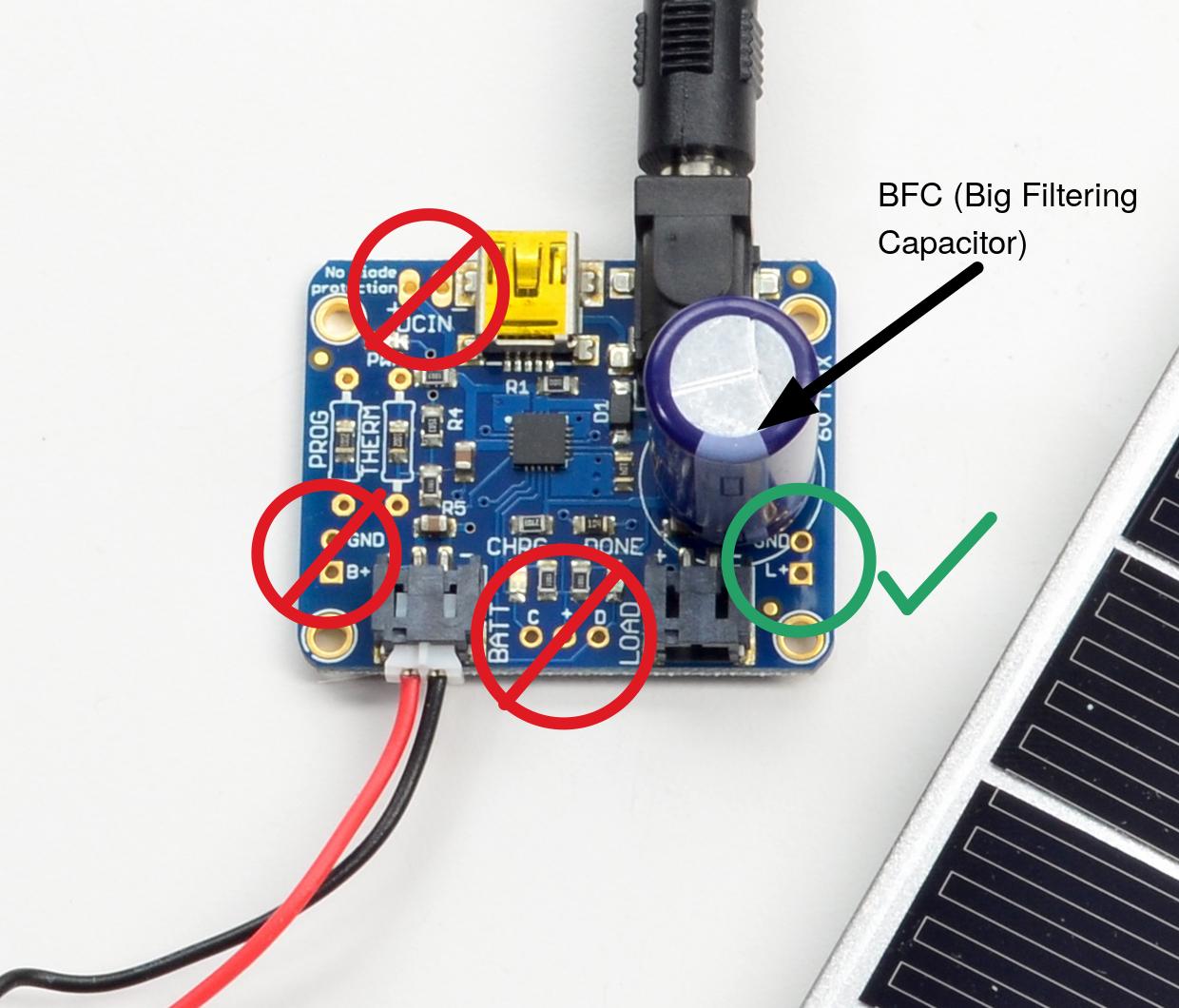
While you're at it, might as well solder the ginormous capacitor to the MCP73871 breakout board. Make sure to get the polarity right! You should also solder a 1x2 pin header on the L+ and GND connections. They're located right next to the ginormous capacitor and will be used to get power off the MCP73871 board.
ESP32 + SHTC3
Let's first hook up the EPS32C3 and the SHTC3 breakout board. Take a look at the pinout for the ESP32C3 and the breakout board pinout for the SHTC3. Sketch on a piece of paper the connections you need to make. Then make them!
Some notes:
- Please keep your wires flat, neat, and short. Use color coding for ground, 3V3, signals, etc.
- Now's a good time to give yourself power (3.3V, not 5V!) and ground rails on your breadboard. They will come in handy later.
- We recommend feeding the SHTC3 breakout with 3V3 rather than using the onboard regulator. Of course, the breakout board website says that the 3Vo pin is an "output", but a look at the actual schematic shows that the pin goes directly to the SHTC3 input. The only question then is whether feeding 3V3 into the regulator on the breakout will hurt the regulator. This is hard to tell from the regulator datasheet. But we tried it and it worked fine, though would be better to just desolder the regulator, or, better yet, design our own board! Stay tuned on that one.
- Where are those I2C pins on the ESP32? Turns out you can use any two GPIO pins for I2C. Pick two that are convenient. But don't use GPIO8/9 or GPIO20/21.
When you're ready, connect the ESP32C3 to your laptop with a USB cable, and if you did it right two LEDs should light up.
Show your wired-up system to a staff member.

Getting some code running
Now let's actually get something running on our microcontroller to see if our software is working. If you haven't already, open up Visual Studio Code and go to the PlatformIO home page. Click on "New Project", give it a good name, and choose "Espressif ESP32-C3-DevKit-M-1" for the board, and "Arduino" for the Framework.
Click "Finish," and then you'll need to wait a few seconds to a few minutes for initialization (you need to be connected to the Internet for this).
NOTE: You may encounter this error, saying that the project could not initialize:
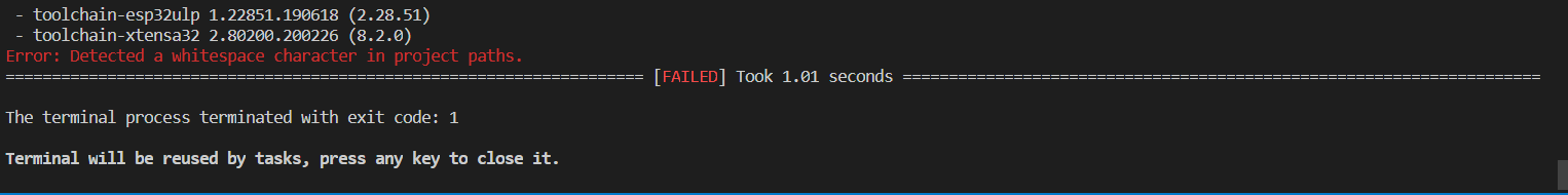
This happens if you have any white space characters in your project file path (for example, if your filepath was C:\Users\Brian Kernighan\...\project, the "Brian Kernighan" part would be a problem, since there's a space). To fix:
- Create a folder named
.platformioin yourC:\folder. - Restart Visual Studio Code
- Uncheck the "Use default location" box
- Save your project in a location where the path doesn't have a white space. For example, you could make a
6190-labsfolder in yourC:\and save everything there.
Once initialization is complete, you might get a pop-up asking "Do you trust the authors of the files in this folder?" Select "Yes."
Default project files
You should now see some files and folders on the left side of your screen (if you don't, click on the Explorer icon, which should be the top one on the sidebar).
platformio.ini, your project configuration file
The first file we'll look at is your platformio.ini file. This will be the configuration file for your project.
Find it in the sidebar, and open it. You should see these four lines:
[env:esp32-c3-devkitm-1]
platform = espressif32
board = esp32-c3-devkitm-1
framework = arduino
main.cpp, where your program lives
Click on the src folder, and you'll see a file named main.cpp. This is your "entry point" file. You can have other .cpp and .h files and include them but your code will always "start" here. Instead of it being your standard int main(void) C-type function entry, we'll instead use the Arduino.h library to allow us to use the setup and loop functions common to that way of programming. As a reminder, since we'll assume you've all done some Arduino-type programming before:
setupruns once at the beginning of the program and we'll use it for a lot of initializations.loopruns continuously as fast as it can/we allow it. This is where the microcontroller will "live" most of the time.
Open main.cpp, delete the existing code, and copy and paste the following code into that main.c file.
#include <Arduino.h>

void setup() {
  Serial.begin(9600);
}

void loop() {
  Serial.printf("Hello World");
  delay(1000);
}
Let's "use" it. First, we need to build the code. Let's take a look at the blue toolbar at the bottom of the screen.

PlatformIO Toolbar
NOTE: If you can't see the toolbar, or it looks different, it may be because you have other VS Code workspaces open (this would only apply to people who have used VS Code previously). Removing those workspaces should fix that issue and get the toolbar to show up.
Build
Verify that you see Default(setup_test) like shown on the toolbar. For a given project, we need to make sure that field is Default(project_name) so that we're building/uploading the correct project. If there is nothing there, that means that you don't have a project open in your VS Code workspace; if it says something different (which may happen as you start to build new projects and move between different ones), you can change it by clicking on that part of the toolbar and selecting the correct project.
Now, click the check mark icon on the toolbar to build our program. If the code compiled successfully, you should see a message saying something like "[SUCCESS] Took 45 seconds" print out in the terminal.
Upload
Next, making sure that you have physically connected your ESP32 to your computer, click on the arrow icon on the toolbar to upload the program to the ESP32.
If everything worked, when you open up the serial monitor (the plug shaped symbol), after a litle bit, you should see the message being printed on repeat.
Let's sense some temp
Now, go back to the PlatformIO home, go to Libraries, search for the "SparkFun SHTC3 Humidity and Temperature Sensor Library", "Add to Project", and select the correct project.
If you did this correctly, in the platformio.ini tab, you should see a new entry under "lib_deps".
Now, let's get some basic code running. Copy/paste the following into your main.cpp:
#include <Arduino.h>
#include "SparkFun_SHTC3.h" // Click here to get the library: http://librarymanager/All#SparkFun_SHTC3
SHTC3 mySHTC3;              // Declare an instance of the SHTC3 class
//function stubs:
void errorDecoder(SHTC3_Status_TypeDef message);
void printInfo();


#define I2C_SDA 2
#define I2C_SCL 3

void setup() {
  Serial.begin(9600);      // Begin Serial
  while(Serial == false){};  // Wait for the serial connection to start up
  Serial.println("SHTC3 Example 1 - Basic Readings");    // Title
  Wire.begin(I2C_SDA, I2C_SCL);
  Serial.print("Beginning sensor. Result = ");  // Most SHTC3 functions return a variable of the type "SHTC3_Status_TypeDef" to indicate the status of their execution
  errorDecoder(mySHTC3.begin());  // To start the sensor you must call "begin()", the default settings use Wire (default Arduino I2C port)
  Serial.println();
  Serial.println("\n\n");
  Serial.println("Waiting for 5 seconds so you can read this info ^^^");

  delay(5000);                                                // Give time to read the welcome message and device ID.
}

void loop() {
  SHTC3_Status_TypeDef result = mySHTC3.update();             // Call "update()" to command a measurement, wait for measurement to complete, and update the RH and T members of the object
  printInfo();                                                // This function is used to print a nice little line of info to the serial port
  delay(190);                                                 // Delay for the data rate you want - note that measurements take ~10 ms so the fastest data rate is 100 Hz (when no delay is used)
}

///////////////////////
// Utility Functions //
///////////////////////
void errorDecoder(SHTC3_Status_TypeDef message){
  switch(message){
    case SHTC3_Status_Nominal : Serial.print("Nominal"); break;
    case SHTC3_Status_Error : Serial.print("Error"); break;
    case SHTC3_Status_CRC_Fail : Serial.print("CRC Fail"); break;
    default : Serial.print("Unknown return code"); break;
  }
}

void printInfo(){
  if(mySHTC3.lastStatus == SHTC3_Status_Nominal){
    Serial.print("RH = ");
    Serial.print(mySHTC3.toPercent()); // "toPercent" returns the percent humidity as a floating point number
    Serial.print("%, T = ");
    Serial.print(mySHTC3.toDegF());   // "toDegF" and "toDegC" return the temperature as a flaoting point number in deg F and deg C respectively
    Serial.println(" deg F");
  }
  else{
    Serial.print("Update failed, error: ");
    errorDecoder(mySHTC3.lastStatus);
    Serial.println();
  }
}
Go thru the code and make sure you can figure out what it's doing. You'll want to update the code to your exact I2C pins. The numbers refer to the GPIO pins, aka "6" is GPIO6 not pin 6.
Build, then Upload the project, and look at the serial monitor. If all is well (wiring, library, etc.) you should see the humidity and temperature printing out like so (obviously different based on where you are at on this big blue marble which we only have one of don't you know so let's take care of it)
RH = 30.62%, T = 73.61 deg F
RH = 30.61%, T = 73.59 deg F
RH = 30.59%, T = 73.64 deg F
RH = 30.57%, T = 73.59 deg F
...
If it isn't printing or giving errors in readout, double check your wiring, and all the other usual suspects one would think about with a sysytem like this. Also, of course, reach out for help on Piazza or with staff!
Do some stuff to make sure those readings make sense and change as a result of perturbations.
To the internet!
Ok instead of having our device read a local sensor, let's instead talk to a server via the internet. Let's replace our code with the code below.
Note a few things:
- There's a lot more going on in this code than the previous two. (It is basically a modified version of some 6.08 code from a lab).
- This code connects to the WiFi. This requires you to put in the valid credentials for a 2.4GHz network. The good ones on the 5th floor lab space (hopefully where you are) are either
EECS_Labs(with no password) or608_24Gwith password608g2020. - To use the campus-wide
MITnetwork, you must first register for a personal password at the MIT wifi onboarding portal. Once you register you can put your personal password in the ESP code along with theMITssid - Once connected this code will send simple HTTP GET requests to a remote server that provides number-based facts in response.
#include <Arduino.h>
#include <WiFi.h> //Connect to WiFi Network
#include <string.h>  //used for some string handling and processing.

void do_http_GET(char* host, char* request, char* response, uint16_t response_size, uint16_t response_timeout, uint8_t serial);
uint8_t char_append(char* buff, char c, uint16_t buff_size);

const int RESPONSE_TIMEOUT = 30000; //ms to wait for response from host
const int GETTING_PERIOD = 5000; //periodicity of getting a number fact.
const uint16_t IN_BUFFER_SIZE = 1000; //size of buffer to hold HTTP request
const uint16_t OUT_BUFFER_SIZE = 1000; //size of buffer to hold HTTP response
char request_buffer[IN_BUFFER_SIZE]; //char array buffer to hold HTTP request
char response_buffer[OUT_BUFFER_SIZE]; //char array buffer to hold HTTP response

uint32_t last_time=0; //used for timing

//wifi network credentials for 6.08 Lab (this is a decent 2.4 GHz router that we have set up...try to only use for our ESP32s)
char network[] = "608_24G";
char password[] = "608g2020";


void setup() {
  Serial.begin(9600); //begin serial
  while (!Serial) {
      delay(100);
  }

  WiFi.begin(network, password);
  //if using channel/mac specification for crowded bands use the following:
  //WiFi.begin(network, password, channel, bssid);
  uint8_t count = 0; //count used for Wifi check times
  Serial.print("Attempting to connect to ");
  Serial.println(network);
  while (WiFi.status() != WL_CONNECTED && count < 6) { //can change this to more attempts
    delay(500);
    Serial.print(".");
    count++;
  }
  delay(2000);  //acceptable since it is in the setup function.
  if (WiFi.isConnected()) { //if we connected then print our IP, Mac, and SSID we're on
    Serial.println("CONNECTED!");
    delay(500);
  } else { //if we failed to connect just Try again.
    Serial.println("Failed to Connect :/  Going to restart");
    Serial.println(WiFi.status());
    ESP.restart(); // restart the ESP (proper way)
  }
  randomSeed(analogRead(A0)); //"seed" random number generator
}

/*-----------------------------------
  Generate a request to the numbersapi server for a random number
  Display the response both on the TFT and in the Serial Monitor
*/
void loop() {
  if ((millis() - last_time) > GETTING_PERIOD) { // GETTING_PERIOD since last lookup? Look up again
    //formulate GET request...first line:
    sprintf(request_buffer, "GET http://numbersapi.com/%d/trivia HTTP/1.1\r\n", random(200));
    strcat(request_buffer, "Host: numbersapi.com\r\n"); //add more to the end
    strcat(request_buffer, "\r\n"); //add blank line!
    //submit to function that performs GET.  It will return output using response_buffer char array
    do_http_GET("numbersapi.com", request_buffer, response_buffer, OUT_BUFFER_SIZE, RESPONSE_TIMEOUT, true);
    last_time = millis();//remember when this happened so we perform next lookup in GETTING_PERIOD milliseconds
  }
}


/*----------------------------------
   char_append Function:
   Arguments:
      char* buff: pointer to character array which we will append a
      char c:
      uint16_t buff_size: size of buffer buff

   Return value:
      boolean: True if character appended, False if not appended (indicating buffer full)
*/
uint8_t char_append(char* buff, char c, uint16_t buff_size) {
  int len = strlen(buff);
  if (len > buff_size) return false;
  buff[len] = c;
  buff[len + 1] = '\0';
  return true;
}

/*----------------------------------
   do_http_GET Function:
   Arguments:
      char* host: null-terminated char-array containing host to connect to
      char* request: null-terminated char-arry containing properly formatted HTTP GET request
      char* response: char-array used as output for function to contain response
      uint16_t response_size: size of response buffer (in bytes)
      uint16_t response_timeout: duration we'll wait (in ms) for a response from server
      uint8_t serial: used for printing debug information to terminal (true prints, false doesn't)
   Return value:
      void (none)
*/
void do_http_GET(char* host, char* request, char* response, uint16_t response_size, uint16_t response_timeout, uint8_t serial) {
  WiFiClient client; //instantiate a client object
  if (client.connect(host, 80)) { //try to connect to host on port 80
    if (serial) Serial.print(request);//Can do one-line if statements in C without curly braces
    client.print(request);
    memset(response, 0, response_size); //Null out (0 is the value of the null terminator '\0') entire buffer
    uint32_t count = millis();
    while (client.connected()) { //while we remain connected read out data coming back
      client.readBytesUntil('\n', response, response_size);
      if (serial) Serial.println(response);
      if (strcmp(response, "\r") == 0) { //found a blank line! (end of response header)
        break;
      }
      memset(response, 0, response_size);
      if (millis() - count > response_timeout) break;
    }
    memset(response, 0, response_size);  //empty in prep to store body
    count = millis();
    while (client.available()) { //read out remaining text (body of response)
      char_append(response, client.read(), OUT_BUFFER_SIZE);
    }
    if (serial) Serial.println(response);
    client.stop();
    if (serial) Serial.println("-----------");
  } else {
    if (serial) Serial.println("connection failed :/");
    if (serial) Serial.println("wait 0.5 sec...");
    client.stop();
  }
}
Upload the code. In the serial monitor, you should see random number facts printing out every few seconds. Your ESP32 does not internally contain all those facts, so the only way it could be printing those would be if it was getting them through the "ether"...so WiFi must be working. Nice. If you have that, that means you're good to move on!
Setting the Stage
Now let's set the stage for the next part...and point our ESP32-C3 to a server where we can store our own data. In this week's problem set you'll set up your very own server, but for now we'll use a central server set up by the staff, that everyone can access.
You'll want to update your loop function to create a POST request instead of a GET request. Though it's cooler to use a POST body to submit your data, for now we'll use query arguments since it's a touch simpler.
Here are the specs:
- The host you are trying to reach is efpi-10.mit.edu
- You need to convert your RH and T from floats to char arrays. sprintf(), similar to what's shown below, is a good way to do that.
- You need to add your kerberos as a parameter.
You can use the query arguments to convey your data (don't need to use a POST body for this one, though you can if you'd like). The important thing though is to use the POST http verb to post data (as opposed to the GET verb we used earlier)
POST /efi_test/rht?temp=70.49&rh=30.54&kerberos=None HTTP/1.1
You actually don't need to change your do_HTTP_GET function, as it doesn't actually care whether it sends a GET or a POST.
void loop() {
  if ((millis() - last_time) > GETTING_PERIOD) { // GETTING_PERIOD since last lookup? Look up again
    //formulate GET request...first line:
    sprintf(request_buffer, "GET http://INSERT_SERVER_AND_STRINGS_HERE HTTP/1.1\r\n", thing1, thing2);
    strcat(request_buffer, "Host: INSERT_SERVER_HERE\r\n"); //add more to the end
    strcat(request_buffer, "\r\n"); //add blank line!
    //submit to function that performs GET.  It will return output using response_buffer char array
    do_http_GET("INSERT_SERVER_HERE", request_buffer, response_buffer, OUT_BUFFER_SIZE, RESPONSE_TIMEOUT, true);
    Serial.println(response_buffer); //print to serial monitor
    last_time = millis();//remember when this happened so we perform next lookup in GETTING_PERIOD milliseconds
  }
}
Recompile the code, reupload, and then see what happens in the serial monitor. Eventually, your code should repeatedly start printing this:
POST http://efpi-10.mit.edu/efi_test/rht?temp=70.82&rh=24.82&kerberos=None HTTP/1.1
Host: efpi-10.mit.edu

HTTP/1.1 200 OK
Server: nginx/1.18.0
Date: Tue, 23 Jan 2024 21:51:51 GMT
Content-Type: text/html; charset=utf-8
Content-Length: 6
Connection: keep-alive

posted
-----------
Once you are getting a "posted" return message, you can check to see your data on the server. Point your browser to:
http://efpi-10.mit.edu/efi_test/rht?kerberos=None
And all your data should list out.
Show your system posting to the server to a staff member.
Look ma no wires
Being hooked up to the laptop all the time is very mid. We can send our data to our cloud server, so let's also get rid go wireless with the power, aka let's go battery-powered.
We'll power our system via a LiPo battery. A single-cell LiPo battery has a nominal voltage of 3.7V (a bit more when fully charged, and decreasing as it discharges).
But eventually the battery will discharge, so we need a way of charging it back up. So we need some sort of integrated circuit to charge the battery. LiPo batteries can be dangerous, so specialized ICs are used to make sure the batteries charge at the right rate and to the right voltage.
But it gets even more complicated. If we're running off of the battery, and the battery gets too discharged, we'd like to be able to plug the system in, and have the system continue working, while the battery is charging. After all, when you plug your phone in to charge, you expect the phone's battery to charge and the phone to still work.
So really what we need is some magical IC (or ICs) to manage the power, directing power to/from the battery, to the system, from the wall, and so on. Sounds complicated.
Luckily, it's complicated but extremely commonly needed, and hence companies have created solutions to do this. These systems go under various interrelated name: battery management system (BMS), power management IC (PMIC), battery chargers, and so on.
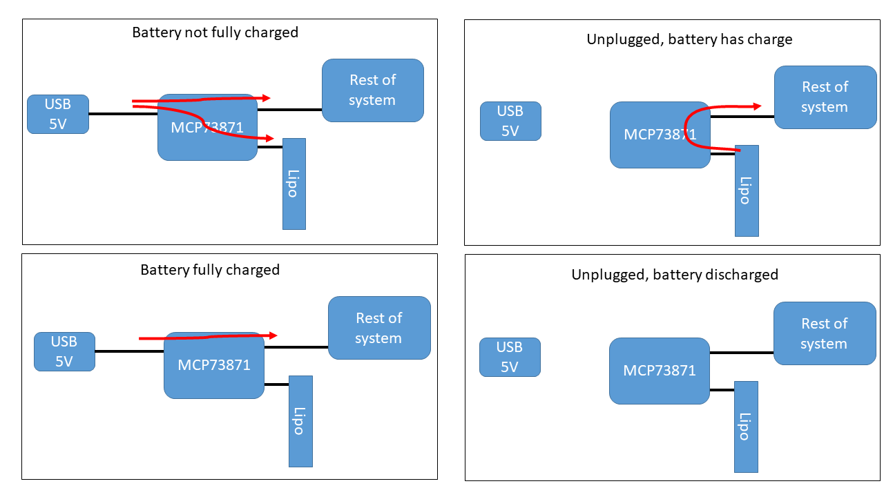
We'll be using the MCP73871. This remarkable little chip (~$2!), includes "load sharing" (aka automatically directing power to the system or the battery), and battery charge management (charge the battery).
Basically, the system operates in a few different modes:
Take your MCP731871 breakout and LiPo battery and hook up the battery to either of the battery terminals on the board (these are a type of "JST" connector, if you want to be cool about it).
Then, connect the board to your computer via a mini-USB cable (or to the wall with a 5v power supply). You should again see two LEDs light up. The Adafruit website for the board tells us what each LED means.
In this configuration, the USB cable (or power supply) is delivering energy to the battery via the MCP71871 to charge up the battery (LiPO batteries are typically only partially charged during shipping, for safety reasons). If you were to leave it in for a while, it would charge up fully, and one of those LEDs would change (remember which one?).
But we also want to power the rest of our system. But do we connect the MCP73871 board to 3V3 or to 5V? Well, the MCP73871 does not have a regulator on it. In fact, it just sends power to the connector at whatever voltage that power is at. So if you are running off battery, the output voltage will be around 3.7V. If you are connected to a 5V power supply input, the output voltage will be around 5V. If you were connected to a 6V solar cell operating in peak sunlight, it would be 6V. Like we said, unregulated.
So in this case, we want to send the power to the 5V input pin on the ESP32C3 because that will then send the power to an onboard regulator, so everything is nice and safe.
With all that squared away, let's make some connections.
Unplug the USB cable (or power supply) and the battery from the MCP718731 board. Then hook up wires from the L+ and GND pin header on the MCP73871 board to the ESP32C3 board.
Then plug in the battery, and the USB cable (or power supply). Now you should have 4 LEDs going across your 3 boards. Check the website. Should be posting data. Congrats, you have a battery-powered IoT weather station!
The MCP73871 board is just dangling from your breadboard, which doesn't look awesome. So take some electrical tape and tape it down nice and firm. While you're at it, tape down the battery as well.
Now, you really have a go-to system.
And so how do we program now?
We now have a bit of an issue. We are powering our ESP32C3 system via the MCP73871 board into the ESP32C3's 5V pin. But if we connect a USB cable from our computer to the ESP32C3 while the power board is connected, then the 5V from the computer's USB will connect to the output of the MCP73871 board, which may be at 3.7V, or 5V, or 6V. This could damage something. Not good.
One option is to disconnect the power board every time we want to program our ESP32C3. I've tried this. It sucks.
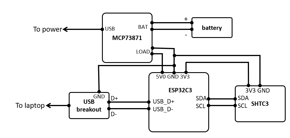
Instead, we'll use a USB breakout to bring just the data lines from the laptop to the ESP32C3, and not connect the 5V from the USB voltage. Kind of like so:
Get a Micro-USB breakout board, and wire the Ground, D+ , and D- pins from that connector to the corresponding pins on the ESP32C3. Your system schematic should now look like this:
Now if you plub in the USB cable to the computer, you should see a COM port show up. But it will probably be a different COM port than what we used earlier in lab. Why?
Because using this approach we bypass the ESP32C3 breakout board's USB-to-UART bridge (a chip that interfaces between your laptop's USB and the ESP32C3's UART pins) and instead connect directly to the ESP32C3's on-board USB.
Finally, we need to tell the ESP32 to use the on-board USB versus the USB-to-UART bridge. To do that, in your platformio.ini file, add the following at the end:
build_flags =
  -DARDUINO_USB_MODE
  -DARDUINO_USB_CDC_ON_BOOT
Now, compile and upload, and you should be posting again.
To make sure you don't mistakenly use the ESP32's USB plug, put a piece of electrical tape over it.
Show your battery-powered system posting to the server to a staff member.
Sensing battery voltage
At this point we should have a battery powered portable temperature/humidity sensor. It would be useful to know how much charge is left in the battery. Let's add battery sensing capabilities to our system.
To estimate the charge left in the LiPo cell, we can measure its voltage and correlate that to a state of charge (SOC) level. That is easier said than done.
The battery's voltage can range between 4.2 volts (100% SOC) and 3.4 volts (~0% SOC). Since the battery voltage is present of the "5V" rail, we just need to measure the voltage present on it. One of the challenges with doing this directly is that the ESP32's adc can only measure voltages between 0V and 2.5V. We need to somehow scale the 5V rail down to 2.5V (otherwise our ESP would just read 2.5V).
We can use a pair of resistors to make a voltage divider. We can then safely measure the scaled down voltage, in our code apply the inverse of our divider ratio, and arrive at the true pre-divider voltage measurement.
So lets just grab any two resistors off the floor, hook up our battery, and fix it in software. Not so fast.
- Since when our battery is charging the MCP passes 5V through to the ESP, our divider must "transform" a 5V supply rail to less than 2.5V.
- We can't just use any two resistors. These two resistors will be permanently attached to our battery. If their resistance is too low, they will quickly discharge our battery, shorten our run-time, and may even turn into an LER. We should design our divider to draw less than 5mW of power.
- The ESP's adc will draw a (very) small amount of current from the output of the resistor divider. Make sure that the equivalent Thévenin resistance of the divider presents a negligible (<10mV) drop when the ESP's adc draws it's sampling current (1uA).
One last hardware thing. We should add a capacitor to the output of the voltage divider to smooth out the voltage measurement. This value is not as critical as the resistors from above. Anything between 1nF and 10uF should work.
Analog to digital conversion
Now that we have conditioned the voltage signal, connect the output of the divider to an available analog GPIO of our ESP32. We wrote some code to help you extract the raw ADC value from the ESP and convert it to a voltage.
/* NOTE: paste the following line at the top of your main.cpp*/
#include "esp_adc_cal.h"
/*                    */


/*----------------------------------
   read_analog_voltage Function:
   Arguments:
      int gpio_pin: GPIO pin number from which to read the analog value
      int num_average: Number of readings to average for smoothing the output
   Return value:
      float: Returns the average voltage reading from the specified GPIO pin in volts
*/
float read_analog_voltage(int gpio_pin, int num_average)
{
  esp_adc_cal_characteristics_t adc_chars; // Structure to store ADC calibration characteristics
  int adc_readings_raw = 0;                // Variable to accumulate raw ADC readings

  // Loop to collect multiple ADC readings for averaging
  for (int i = 0; i < num_average; i++)
  {
    adc_readings_raw += analogRead(gpio_pin); // Add current reading to total
    delayMicroseconds(10);                    // Tiny delay to allow for ADC settling
  }
  adc_readings_raw = adc_readings_raw / num_average; // Calculate average of readings

  // Determine the ADC unit based on the GPIO pin number
  adc_unit_t current_adc = ADC_UNIT_1; // Default ADC unit
  if (gpio_pin == 5)
  {
    current_adc = ADC_UNIT_2; // Change ADC unit for specific pins, if necessary
  }

  // Characterize the ADC at 11 dB attenuation and 12-bit width for accurate voltage conversion
  esp_adc_cal_characterize(current_adc, ADC_ATTEN_DB_11, ADC_WIDTH_BIT_12, 1100, &adc_chars);

  // Convert the average raw reading to voltage in volts, using calibration characteristics
  return (esp_adc_cal_raw_to_voltage(adc_readings_raw, &adc_chars) / 1000.0);
}
This function takes the GPIO number of the analog pin and returns a floating point value of the voltage present on that pin. It will sample the pin num_average times and average the result.
This function returns the voltage present on the specified analog GPIO pin. Make sure to "undivide" the voltage divider ratio to get the actual battery voltage.
Make sure your system is correctly measuring voltage (get a multimeter and actually confirm). It should be reasonably close (within 5%).Depending on your battery's charge, your system should measure a voltage between 3.4 and 4.2 volts. If your system is charging, it should say ~5 volts.
Estimating SOC
Now that we know our battery's voltage, we can estimate the SOC by referencing the battery's SOC vs Voltage curve. Once again, we wrote some code to help you with this.
/*----------------------------------
   estimateSoC Function:
   Estimates the State of Charge (SoC) of a battery based on its voltage using a polynomial approximation.

   Arguments:
      float voltage: The voltage of the battery for which the SoC is to be estimated.

   Return value:
      float: The estimated state of charge as a percentage. Returns 0.00 for voltages below 3.36V,
      100.0 for voltages above 4.19V, and a polynomially estimated value for voltages in between.

   Description:
   This function estimates the battery's state of charge based on its voltage. For voltages outside
   the range of 3.36V to 4.19V, it returns fixed values of 0% and 100% respectively, assuming the battery
   is fully discharged below 3.36V and fully charged above 4.19V. For voltages within this range, it uses
   a polynomial approximation to estimate the SoC. The polynomial coefficients are hardcoded into the function,
   and Horner's method is used for efficient evaluation of the polynomial.
*/
float estimateSoC(float voltage)
{
  // Check for voltage below the minimum threshold
  if (voltage < 3.36)
  {
    return 0.00; // Battery is considered fully discharged
  }
  // Check for voltage above the maximum threshold
  else if (voltage > 4.19)
  {
    return 100.0; // Battery is considered fully charged
  }
  else
  {
    // Coefficients from x^0 to x^n (n=28), ordered from the constant term to the highest degree term
    float coeffs[] = {
        -2.6858243206578782e+006, 2.0774032211986852e+006, -2.5797025510029204e+005,
        -2.7384859936901976e+004, -2.0356400543884891e+004, -4.3637349720995298e+003,
        -6.0209190224388180e+002, 1.5494493076861318e+003, 3.1532338161500957e+002,
        -6.0983530208466711e+001, -2.8579916186826772e+001, -3.2922413988527368e+000,
        -7.0598853736499545e-002, 1.0836823564467801e-001, 7.9485504289078607e-002,
        2.6678087720686725e-002, 1.9969044213183468e-003, -1.0623124118792605e-003,
        -4.3496263991990445e-004, -4.4513085051829619e-005, -4.2865152117283100e-006,
        2.9641667579656704e-006, 1.1131398755715542e-006, 1.5553129916959425e-007,
        -1.4955696986474453e-008, -1.2888367678610349e-008, -1.4900367931693147e-009,
        5.1223012659240823e-010, -1.1140487469897243e-011}; // r squared = 0.997268729 lets go!
    int num_coeffs = sizeof(coeffs) / sizeof(coeffs[0]);

    // Evaluate the polynomial at the given voltage using Horner's method for efficient computation
    float result = 0;
    for (int i = num_coeffs - 1; i >= 0; --i)
    {
      result = result * voltage + coeffs[i];
    }

    return (float)result; // Return the computed result as a float
  }
}
This function uses a best-fit polynomial to approximate the battery SOC from its voltage. It uses Horner's method to efficiently calculate the result of the polymonial expansion.
Depending on what voltage your system measures, the resultant SOC should be between 0% and 100%.
Tying it all together
Let's finish this lab.
Your system should still make POST requests with the temperature and humidity as it did above. Now, add another query argument for the SOC. When all is said and done, your system should make a request with 4 query arguments:
- temp=...
- rh=...
- kerberos=...
- soc=...
Once you see your data being posted to the server and can view it on the webpage, you'r finished! In EX01 we'll change from the efpi-10 endpoint to your own RPi, and use those logs to verify that your system is working.