Lab 5
Please Log In for full access to the web site.
Note that this link will take you to an external site (https://shimmer.mit.edu) to authenticate, and then you will be redirected back to this page.
Overview
Today you're going to get some experience with the Joulescope. Power should be at the front of everyone's mind on this project even if you're not "doing the power part," so use this lab to develop some fluency in these concepts. For today, you should work in a team of about 3 or 4. Our class/team size is about ten. We want three teams. Split up and do so in a way that is different from the original two teams.
We'll study power in some devices using the Joulescope in the following situations:
- An LED being driven from USB bus voltage (5V) with an in-series variable resistor.
- The ESP32-C3 with some basic LED flashing code.
- The ESP32-C3 in different modes of operation (Wifi on, Wifi transmitting, light sleep, deep sleep)
- A photovoltaic cell driving a few different loads.
JouleScope Setup
Here's the Joulescope (shown below). There are three of them in lab. They are very nice system tools. Treat them with respect.
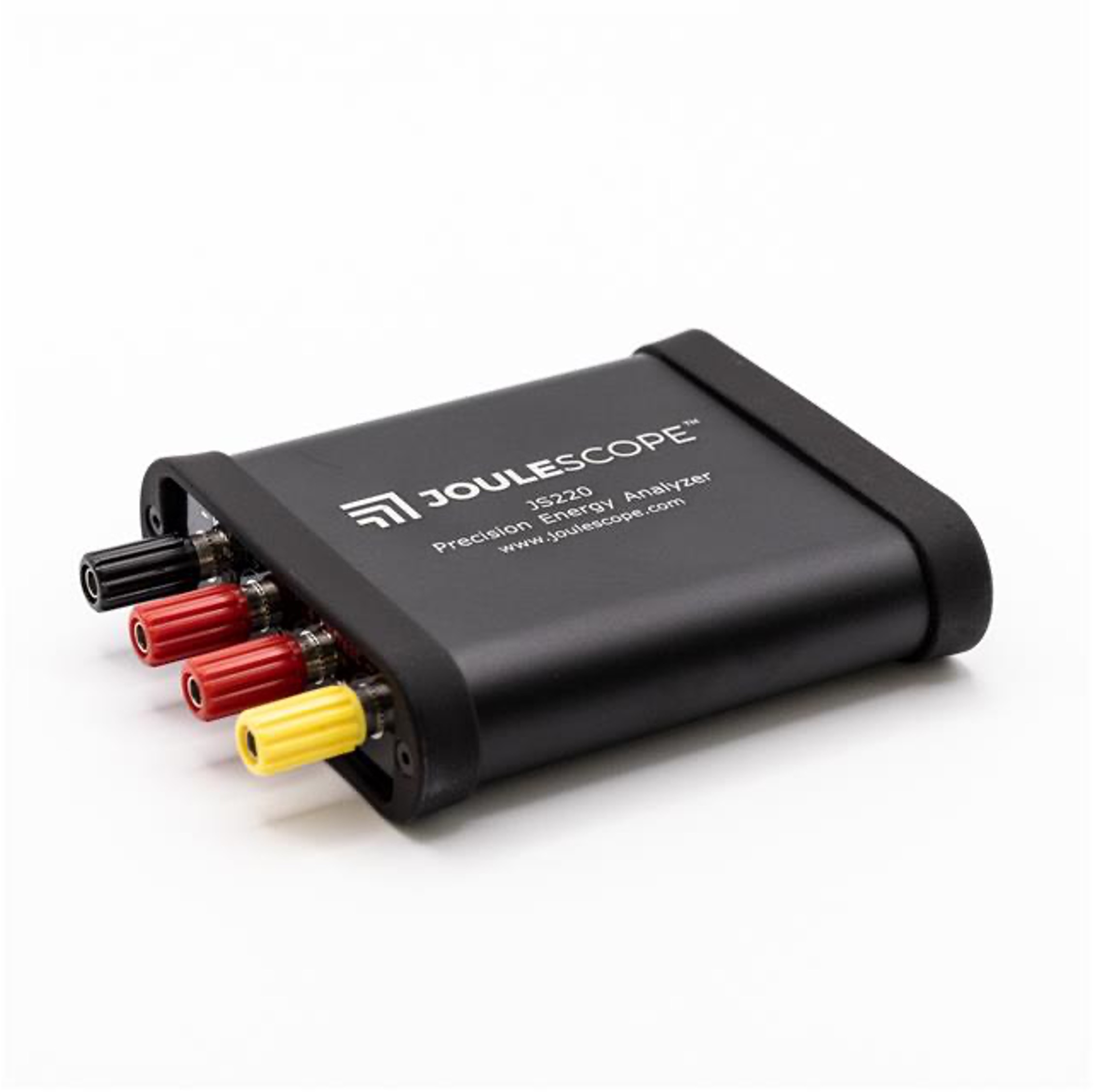
As we discussed in lecture, the Joulescope is an impressive instrument which, when hooked up correctly, will utilize an internal high-precision high-sample-rate ADC to make measurements of the voltage across a portion of a circuit as well as the current into that system. It might seem like what this is doing is not that hard, but the devil is in the details. It is pretty easy to make a power measurement system that works ok-ish for a limited range of power. It is much, much harder to make one that can dynamically adjust itself for a wide-range of powers as the Joulescope does; it has some fantastic engineering in it.
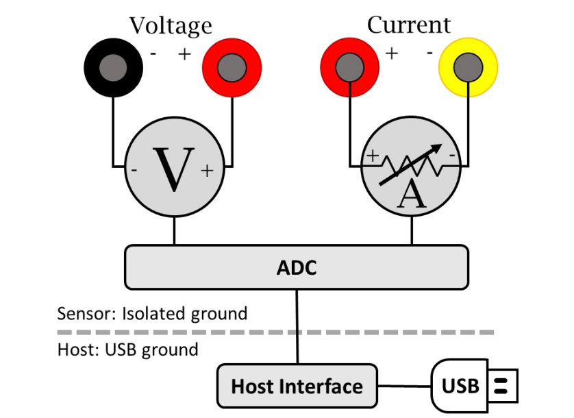
An approximatey "high-level" schematic of the system is shown below:
First task at hand is to get the software to work with our Joulescope. Now maybe I just have really low standards from a lifetime of using hardware design and measurement tools, but I'm blown away by how well this Joulescope software works. Go to their website here. Download the software for the JS220 for your appropriate system. It should just work, but let us know if you have any issues installing.
Once you've got it, open it up and then plug in your Joulescope. For lab today we'll largely be concerned with using two "widgets" the multimeter and the waveform (turn them on from the Widgets pull-in in the top menu.)
All these different widgets kinda show the same data (all of which is just derived from the voltage and current measurments), but they give it to us in different formats to make it easier to consume. If you just want rough ideas of power being consumed (or currnet or whatever), you can look at the "multimeter". If you want to see and measure tiny "blips" of power consumption like from a transfer of data over Wifi, the waveform viewer (which can be saved btw) would be the choice.
The widgets should just start working when you plug in the Joulescope. Again let us know if there's any issues. The readings won't make much sense until you're actually hooked up though so don't freak if you're getting nanoWatts.
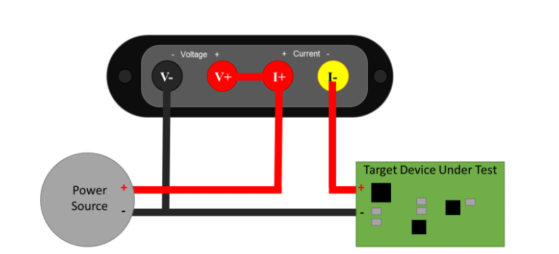
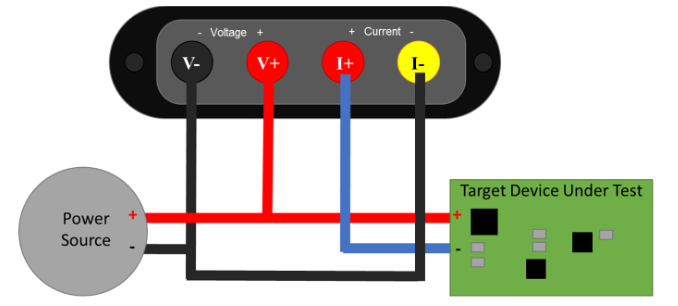
As mentioned in class, there's two ways to measure power consumption (and specifically the current portion), a high-side measurement or a low-side measurement. The two options are shown below, but for today we'd recommend you measure using a high-side configuration.
High-Side Measurement Hookup:
Low-Side Measurement Hookup:
A Simple First Circuit
For a first circuit, just to get our feet wet, let's build the following:
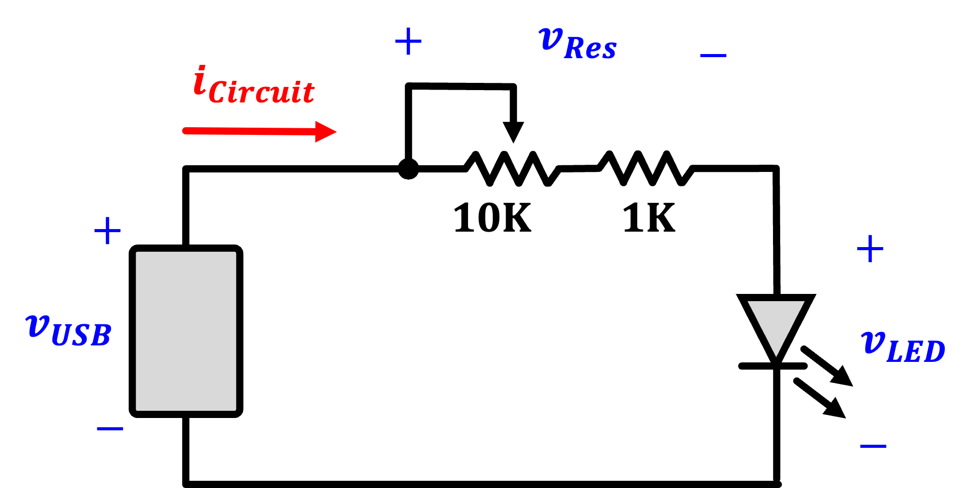
The v_{USB} source should be from the little green breakout boards that we used earlier in the class. We have a few ones for your use (also breadboards, resistors, etc...). Use a fixed 1K resistor and a variable 10K resistor to regulate the flow of current into a red LED (or really any LED). What the circuit should do, at a high level, is vary the brightness of the LED. Build it, power it from your computer or whatever, and just verify it works. When that is done, integrate the Joulescope into it to make some measurements.
Make a high-side measurement of the full circuit's power consumption (resistors and all) by integrating the Joulescope into it. Measure the voltage across the entire resistor-LED system and the current through it. In this placement, the voltage should largely be constant since it is what the USB is providing. You should see the current, and therefore power, vary significantly as you sweep the potentiometer.
After that is done, measure the voltage across the LED specifically while still measuring the current through the whole system. This should now tell you what power the LED on its own is consuming. It should, hopefully if their is a rational god, be less than the number you're getting when you measure what the entire circuit is consuming. Ok noice. Onto the next circuit.
The ESP32-C3
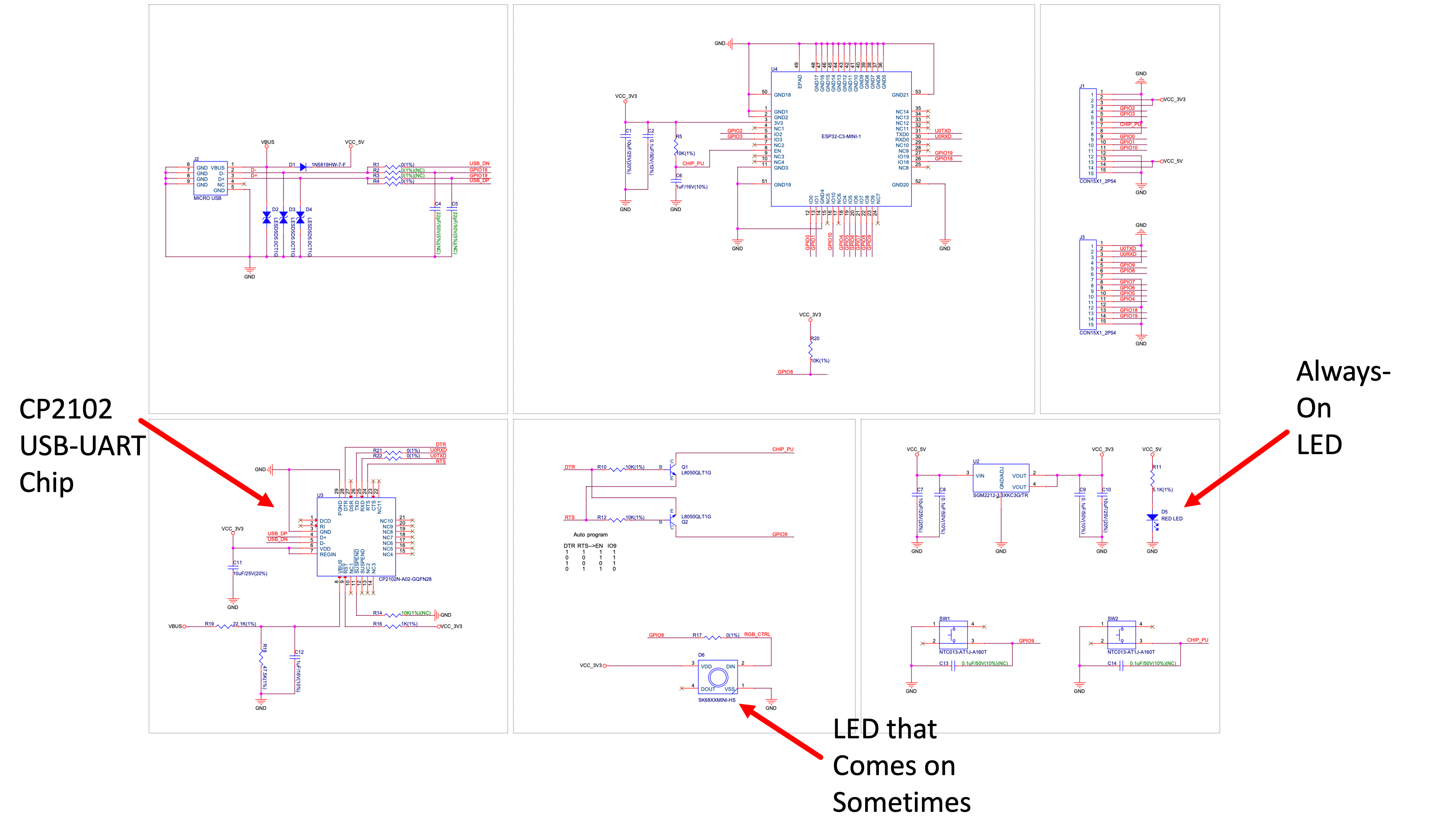
The ESP32-C3 is capable of some pretty interesting behavior related to its power consumption. Unfortunately, some of this capability can be obfuscated when on the Devkit M1 we've been using in class. In addition to the ESP32 C3 (the SOC itself), there are several other parts on the board that are also consuming power including:
- The CP2102 USB-to-UART programming chip (consuming about 0.9 mA @5V)
- The always-on RED power supply indicator LED (consuming about 0.6 mA at @5V)
- That weird RGB LED that sometimes comes on and can be very bright...(if it is bright it is pulling at least several mA at 3.3V if not more)
They're shown in the Devkit schematic below:
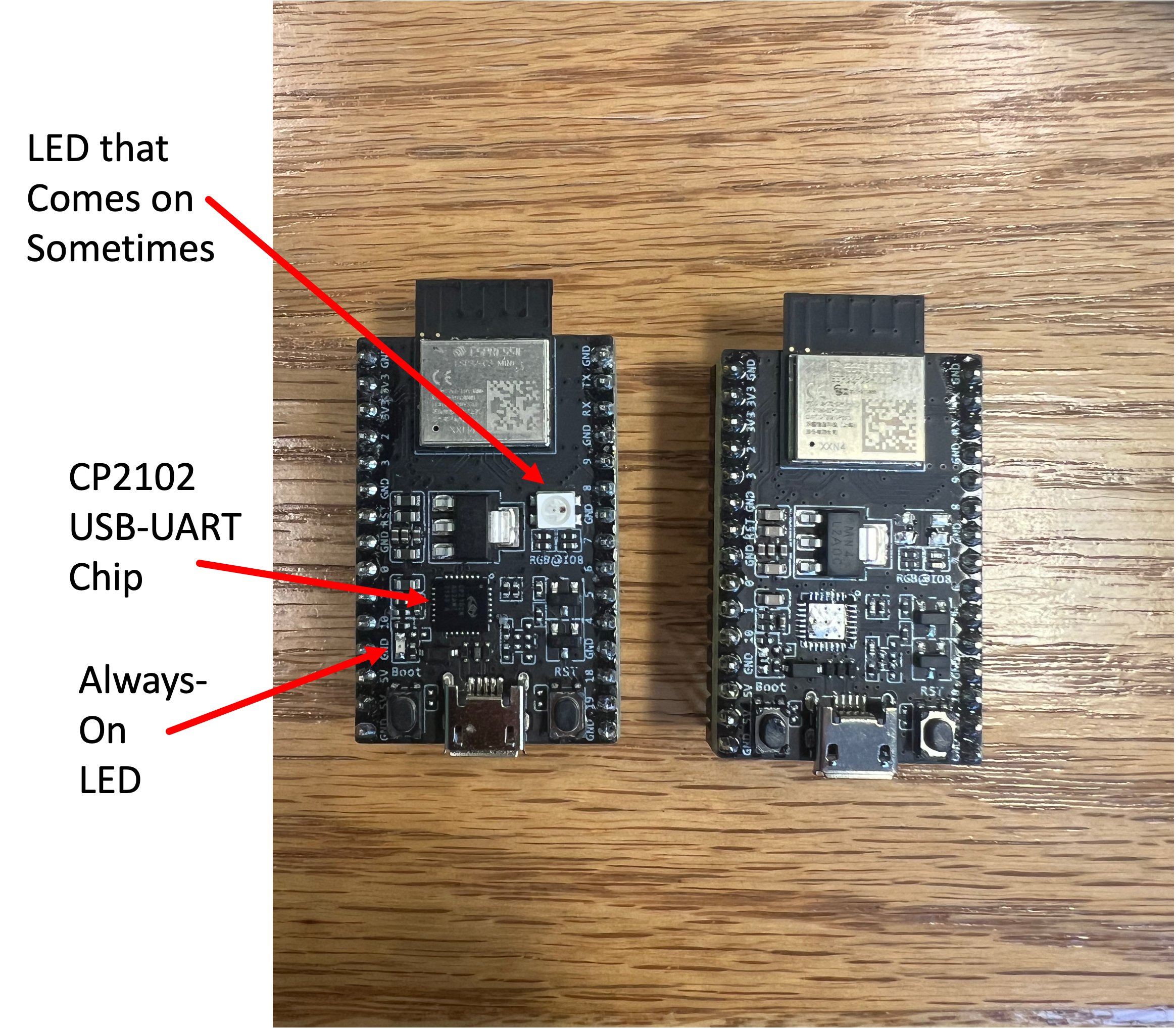
We don't want those parts there. They're distractions. So let's get rid of them....or more correctly, I'll get rid of them for you.
I went ahead and pulled the parts off of three of the devboards which you are to use in this lab. You can see what is missing in the picture below. Left is the original. Right is the one I "improved."
For a programming platform we're basically going to go with exactly what we had before. Have the one of those microUSB breakouts connect to the ESP32C3. In particular (as a refresher):
- VBUS should connect to ESP 5V
- GND should connecto to ESP GND
- D+ should connect to ESP GPIO 19
- D- should connect to ESP GPIO 18
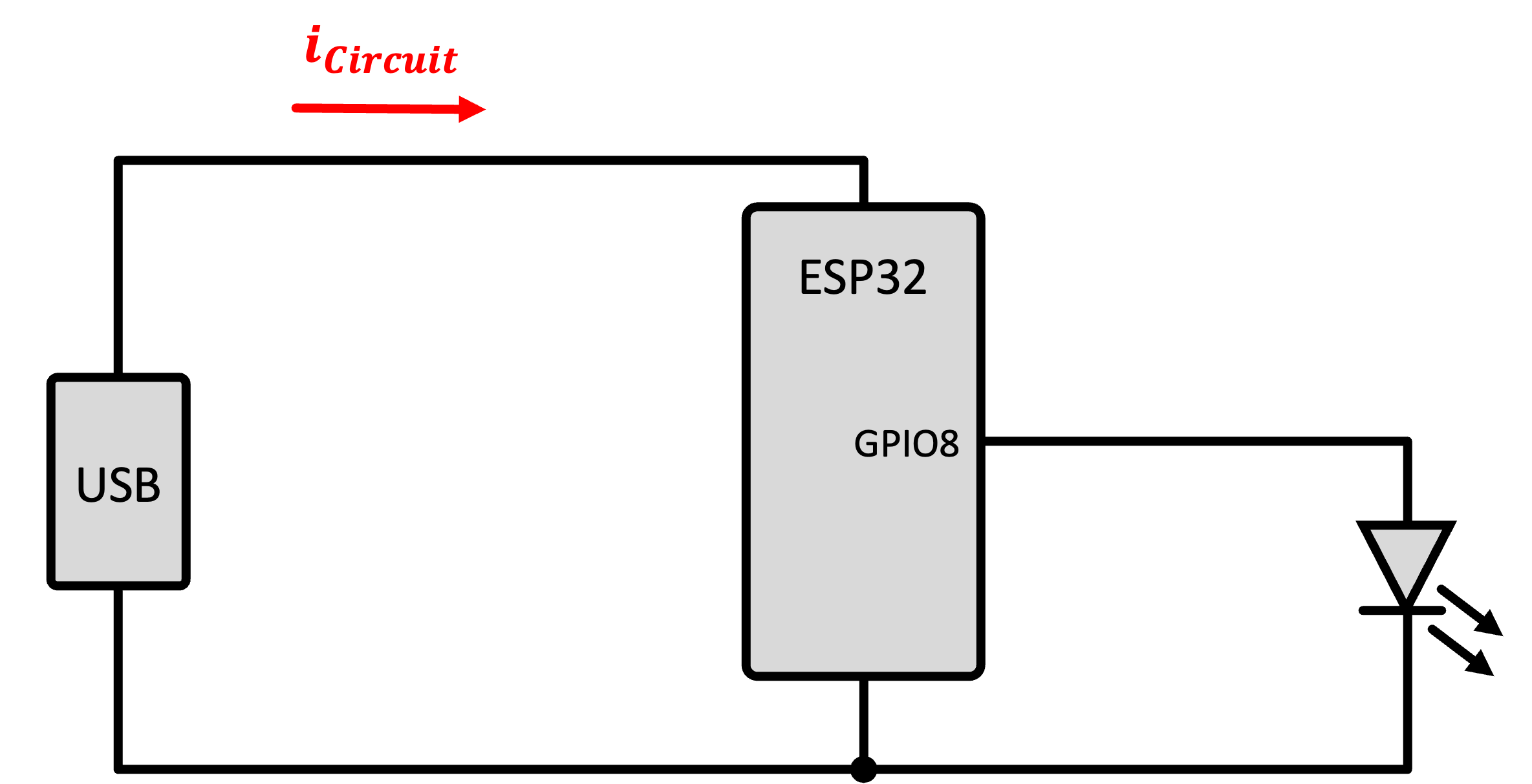
In addition, get a blue or white LED and hook it up to GPIO 8 on the ESP32 like shown below. We're going to flash some LED.
Make a new platform.io project. Make sure you select an Arduino one, select the ESP32-C3 Devkit M1, yada yada, etc... Once in the project, make sure to add the following lines to your platform.ini file:
monitor_speed=9600
build_flags =
  -DARDUINO_USB_MODE
  -DARDUINO_USB_CDC_ON_BOOT
For code, let's use this short, sweet simple program that flashes the LED. Program it to make sure it is even working.
#include <Arduino.h>

int state;
void setup() {
  Serial.begin(9600);
  // while (!Serial);
  Serial.printf("Starting up!\n");
  pinMode(8,OUTPUT);
  state = 0;
  digitalWrite(8,state);
}

void loop() {
  state = !state;
  if (state){
    Serial.printf("LED ON\n");
  }else{
    Serial.printf("LED OFF\n");
  }
  digitalWrite(8,state);
  delay(1000); // on then off 1000 ms...so 0.5Hz flashing
}
Now once you're sure the flashing is good, integrate the Joulescope in so that you're measuring the power consumed by the ESP32-C3. Watch the plot of the voltage, current, and power. You should see very distinctively different regions of power consumption. What do the high and low regions correspond to?
Once that makes sense, go in and change your code so that the LED is flashing 100 times a second instead of once a second (also comment out the two print statements so you don't clog your serial monitor). Once this is done, your eye will barely be able to keep up and instead see a seemingly steady light, or perhaps, if looked at indirectly, just the slighest soupçon of a flicker using the rods of your peripheral vision. But the Joulescope should be able to keep up. It should be able to give you a plot of the instantaneous power being used by your ESP32 because of it either driving or not driving the LED. Very cool.
The ESP32 Doing Other Things
Flashing an LED is fine but a little artificial. What we wanted the last part to demonstrate is that software can cause differences in the power being used by the ESP32. Let's see this in a more "real-world" example.
Consider the code below does a few things. It is a variant of the same code you used in Week 1 but with some modifications. Roughly speaking it:
- It runs on a cycle.
- On the first cycle of every ten, it connects to the WiFi and gets a number fact from numbersapi.com and then spits that out over Serial.
- Every other cycle it flashes the LED on GPIO 8 for 500 ms
- Every tenth cycle, it sends the ESP32 C3 into a deep sleep for 3 seconds.
- For other cycles excluding the every tenth, it instead sends the ESP32 C3 into a light sleep for 3 seconds (timing set in the
setup)
This code is a very simple (and perhaps uselessly short) example of putting the ESP32 C3 through its paces for different power modes and how you may be able to utilize it for the project. Run the updated code and study the power consumption in the different modes. Pay particular attention to the different sleep modes and the activity during hte Wifi transactions. Make notes of the different numbers (lowest power, highest power, etc). Try to tie them up with their different modes! Get a plot of the ESP32 performing WiFi requests and going into different sleep modes
#include <Arduino.h>
#include <WiFi.h> //Connect to WiFi Network
#include <string.h>  //used for some string handling and processing.

void do_http_GET(char* host, char* request, char* response, uint16_t response_size, uint16_t response_timeout, uint8_t serial);
uint8_t char_append(char* buff, char c, uint16_t buff_size);

const int RESPONSE_TIMEOUT = 30000; //ms to wait for response from host
const int GETTING_PERIOD = 5000; //periodicity of getting a number fact.
const uint16_t IN_BUFFER_SIZE = 1000; //size of buffer to hold HTTP request
const uint16_t OUT_BUFFER_SIZE = 1000; //size of buffer to hold HTTP response
char request_buffer[IN_BUFFER_SIZE]; //char array buffer to hold HTTP request
char response_buffer[OUT_BUFFER_SIZE]; //char array buffer to hold HTTP response

uint32_t last_time=0; //used for timing

//wifi network credentials for 6.08 Lab (this is a decent 2.4 GHz router that we have set up...try to only use for our ESP32s)
char network[] = "EECS_Labs";
char password[] = "";

void test_message(){
  WiFi.begin(network, password);
  //if using channel/mac specification for crowded bands use the following:
  //WiFi.begin(network, password, channel, bssid);
  uint8_t count = 0; //count used for Wifi check times
  Serial.print("Attempting to connect to ");
  Serial.println(network);
  while (WiFi.status() != WL_CONNECTED && count < 6) { //can change this to more attempts
    delay(500);
    Serial.print(".");
    count++;
  }
  //delay(2000);  //acceptable since it is in the setup function.
  if (WiFi.isConnected()) { //if we connected then print our IP, Mac, and SSID we're on
    Serial.println("CONNECTED!");
    delay(500);
    //formulate GET request...first line:
    sprintf(request_buffer, "GET http://numbersapi.com/%d/trivia HTTP/1.1\r\n", random(200));
    strcat(request_buffer, "Host: numbersapi.com\r\n"); //add more to the end
    strcat(request_buffer, "\r\n"); //add blank line!
    //submit to function that performs GET.  It will return output using response_buffer char array
    do_http_GET("numbersapi.com", request_buffer, response_buffer, OUT_BUFFER_SIZE, RESPONSE_TIMEOUT, true);
  } else { //if we failed to connect just Try again.
    Serial.println("Failed to Connect :/  Will try next time.");
    Serial.println(WiFi.status());
    //ESP.restart(); // restart the ESP (proper way)
  }
}

int state;
void setup() {
  Serial.begin(9600);
  //while (!Serial);
  Serial.printf("Starting up!\n");
  pinMode(8,OUTPUT);
  state = 0;
  digitalWrite(8,state);
  randomSeed(analogRead(A0)); //"seed" random number generator
  esp_sleep_enable_timer_wakeup(3000000); // how long to sleep.
}

void loop() {
  Serial.printf("I'm up!\n");
  if (state==0){ //once in ten cycles get a number fact over WiFi
    test_message();
  }
  state+=1;
  state%=10;
  Serial.printf("%d\n",state);
  digitalWrite(8,state%2);
  delay(500);
  Serial.printf("going to sleep\n");
  if (state==10){
    esp_deep_sleep_start();
    //deep sleep will effectively restart the system (everything turns off)
  }else{
    esp_light_sleep_start();
    //light sleep *should* just come back here when finished
  }
  Serial.printf("Back from sleeping!\n");
}


/*----------------------------------
   char_append Function:
   Arguments:
      char* buff: pointer to character array which we will append a
      char c:
      uint16_t buff_size: size of buffer buff

   Return value:
      boolean: True if character appended, False if not appended (indicating buffer full)
*/
uint8_t char_append(char* buff, char c, uint16_t buff_size) {
  int len = strlen(buff);
  if (len > buff_size) return false;
  buff[len] = c;
  buff[len + 1] = '\0';
  return true;
}

/*----------------------------------
   do_http_GET Function:
   Arguments:
      char* host: null-terminated char-array containing host to connect to
      char* request: null-terminated char-arry containing properly formatted HTTP GET request
      char* response: char-array used as output for function to contain response
      uint16_t response_size: size of response buffer (in bytes)
      uint16_t response_timeout: duration we'll wait (in ms) for a response from server
      uint8_t serial: used for printing debug information to terminal (true prints, false doesn't)
   Return value:
      void (none)
*/
void do_http_GET(char* host, char* request, char* response, uint16_t response_size, uint16_t response_timeout, uint8_t serial) {
  WiFiClient client; //instantiate a client object
  if (client.connect(host, 80)) { //try to connect to host on port 80
    if (serial) Serial.print(request);//Can do one-line if statements in C without curly braces
    client.print(request);
    memset(response, 0, response_size); //Null out (0 is the value of the null terminator '\0') entire buffer
    uint32_t count = millis();
    while (client.connected()) { //while we remain connected read out data coming back
      client.readBytesUntil('\n', response, response_size);
      if (serial) Serial.println(response);
      if (strcmp(response, "\r") == 0) { //found a blank line! (end of response header)
        break;
      }
      memset(response, 0, response_size);
      if (millis() - count > response_timeout) break;
    }
    memset(response, 0, response_size);  //empty in prep to store body
    count = millis();
    while (client.available()) { //read out remaining text (body of response)
      char_append(response, client.read(), OUT_BUFFER_SIZE);
    }
    if (serial) Serial.println(response);
    client.stop();
    if (serial) Serial.println("-----------");
  } else {
    if (serial) Serial.println("connection failed :/");
    if (serial) Serial.println("wait 0.5 sec...");
    client.stop();
  }
}
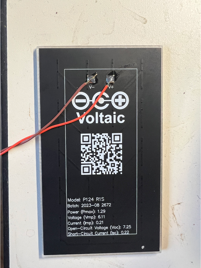
Solar Cell Analysis
As a final task, have your team grab one of the photovoltaic cells we have already pre-soldered wires onto. Notice the specs on the back of this particular cell say that its Pmax is 1.29W. That is a very hopeful number. This panel will likely deliver 1.29W when under very bright, direct sunlight and when you are using the element at its maximum power point that we talked about in class. In lab today we're going to use the cell under room lighting and you will be super surprised at just how awful that is. If you get a few mW out of it, that'll probably be something to celebrate.
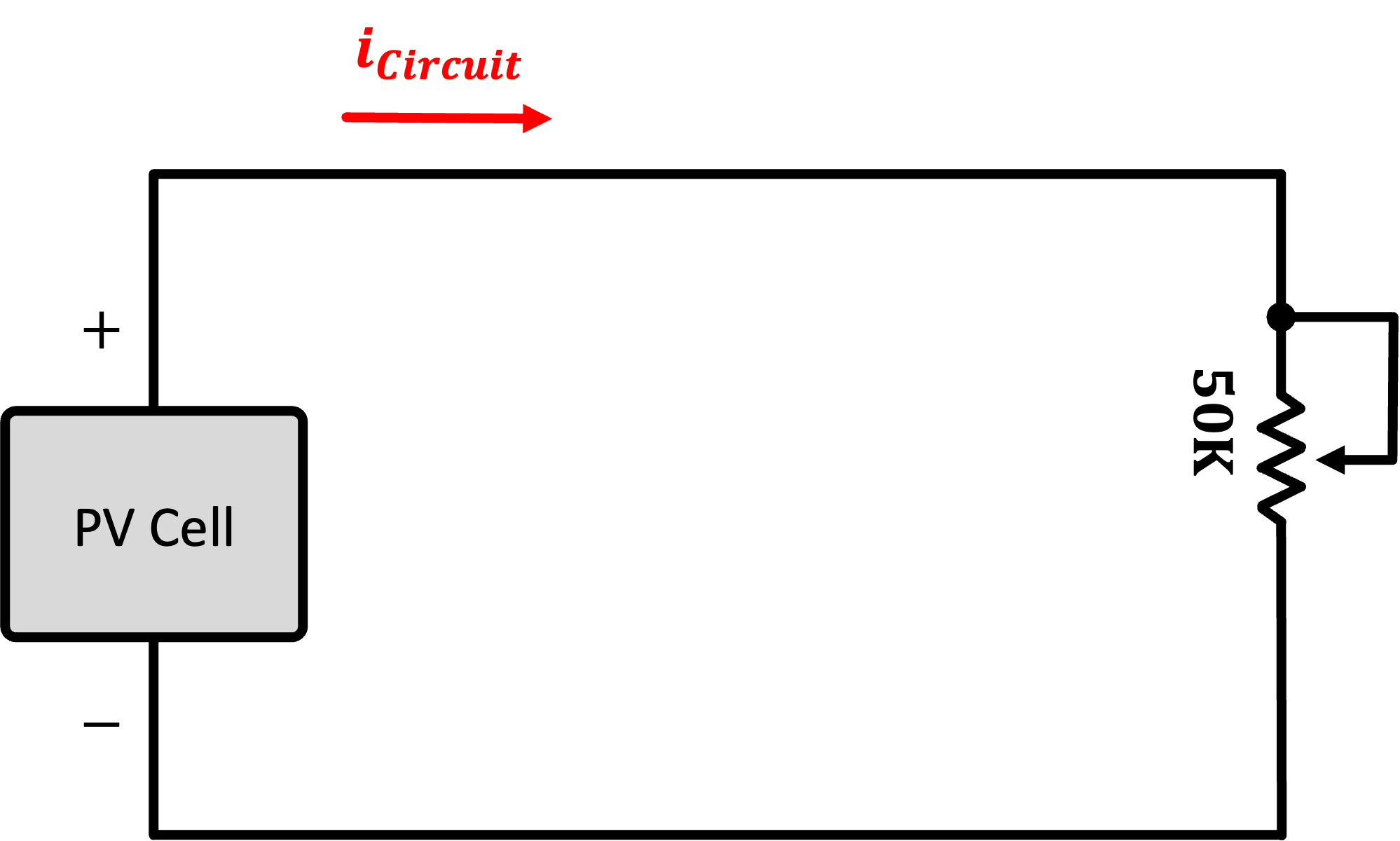
A Variable Load
So as a first circuit, grab a potentiometer (I think a 50K is usable), and measure the power consumed by it (or alternatively the power supplied by the PV cell, same difference). While monitoring the power, vary the potentiometer from one extreme to another. At both extremes you should see minima of power (it might not quite be 0, but it'll be down there). Somewhere in the middle of the potentiometer range, you should be able to find a point where maximum power is being delivered to the resistor. This is the maximum power point.
Make note of this MPP and also try to see how it varies as you put more light on it (perhaps your cellphone, or if the new Schwarzman College of Computing is reflecting the blinding rays sunshine into the room) maybe you can actually get some actual power out of it.
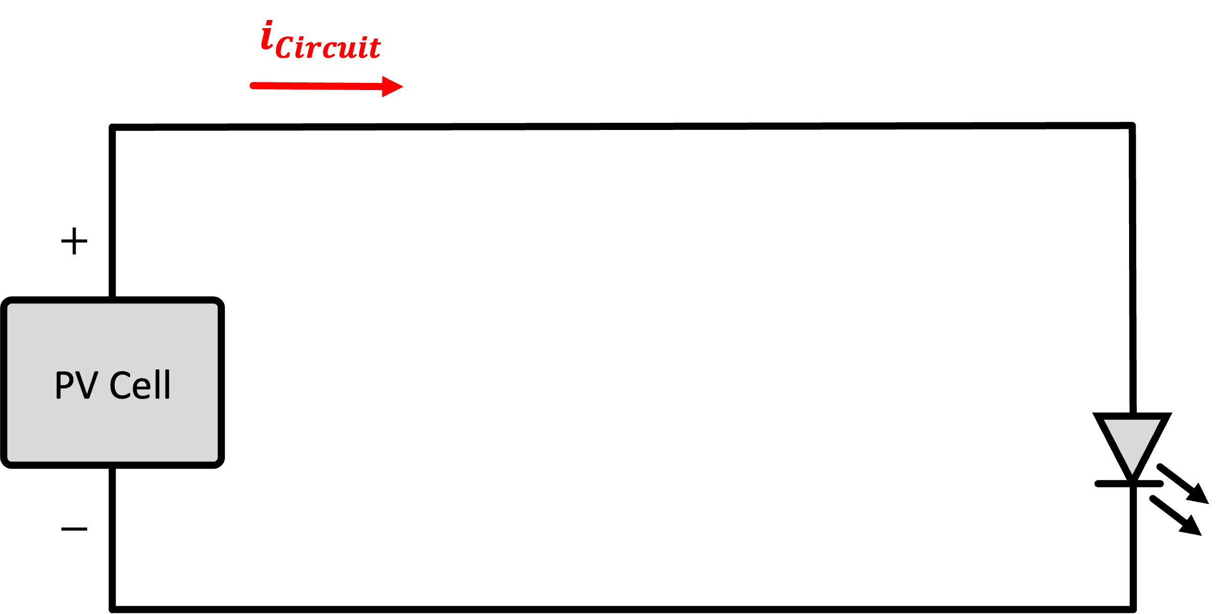
A Fixed Load
In the previous circuit you actually adjusted the load to satisfy the PV cell's characteristics. Not all devices in life can be varied like the potentiometer. Consider another diode...this time an LED, a cousing of the PV cell, just used differently and design to give off light from electrical energy rather than make electrical energy from light. This LED has its own I-V curve that is non-variable. When you assemble a circuit of the PV cell driving this LED you will now have essentially two somewhat stubborn devices trying to exchange energy, and their ability to do so with a high efficiency (such as at the MPP of the cell) may just not be possible.
Build the circuit below. Don't worry about a current-limiting resistor. Unless you are outside or getting beams from Schwarzman, there's no way the cell will be generating enough to burn the LED out. Try to see what power you can harvest from the cell. Can you get the LED to light?
Team Meeting
Use the remaining lab time to do team work. In particular, you may want to go over the users guide to me documents from the team members.