Lab 5
Please Log In for full access to the web site.
Note that this link will take you to an external site (https://shimmer.mit.edu) to authenticate, and then you will be redirected back to this page.
Learning Objectives
Today's lab will focus on assembling and testing your sensor boards. We'll assemble your boards and then undertake various activities with them.
Our accelerometer
This first board of yours is a 3-axis accelerometer, meaning it measures motion in X-, Y-, and Z-directions simultaneously. We'll also refer to it occasionally as an IMU, or inertial measurement unit.
We'll talk in lecture at some point about what's inside this chip, but it's pretty amazing. There is an actual tiny little mass on tiny little springs, and when that mass experiences acceleration, it moves (F=mA, remember?), deforming the springs, which we can measure electrically. These devices are insanely sensitive1
True IMUs measure not just acceleration but also rotation, magnetometry (to find North, for example). Ours is pretty basic (just acceleration), but it is still a super-duper powerful IC. It has alot on on-board computation to add value to an overall system. We're only going to touch the surface of what it can do, but if you end up using an IMU in your semester project, you'll want to dig in a bit deeper into what it can do.
OK, let's get started.
Plugin Installation
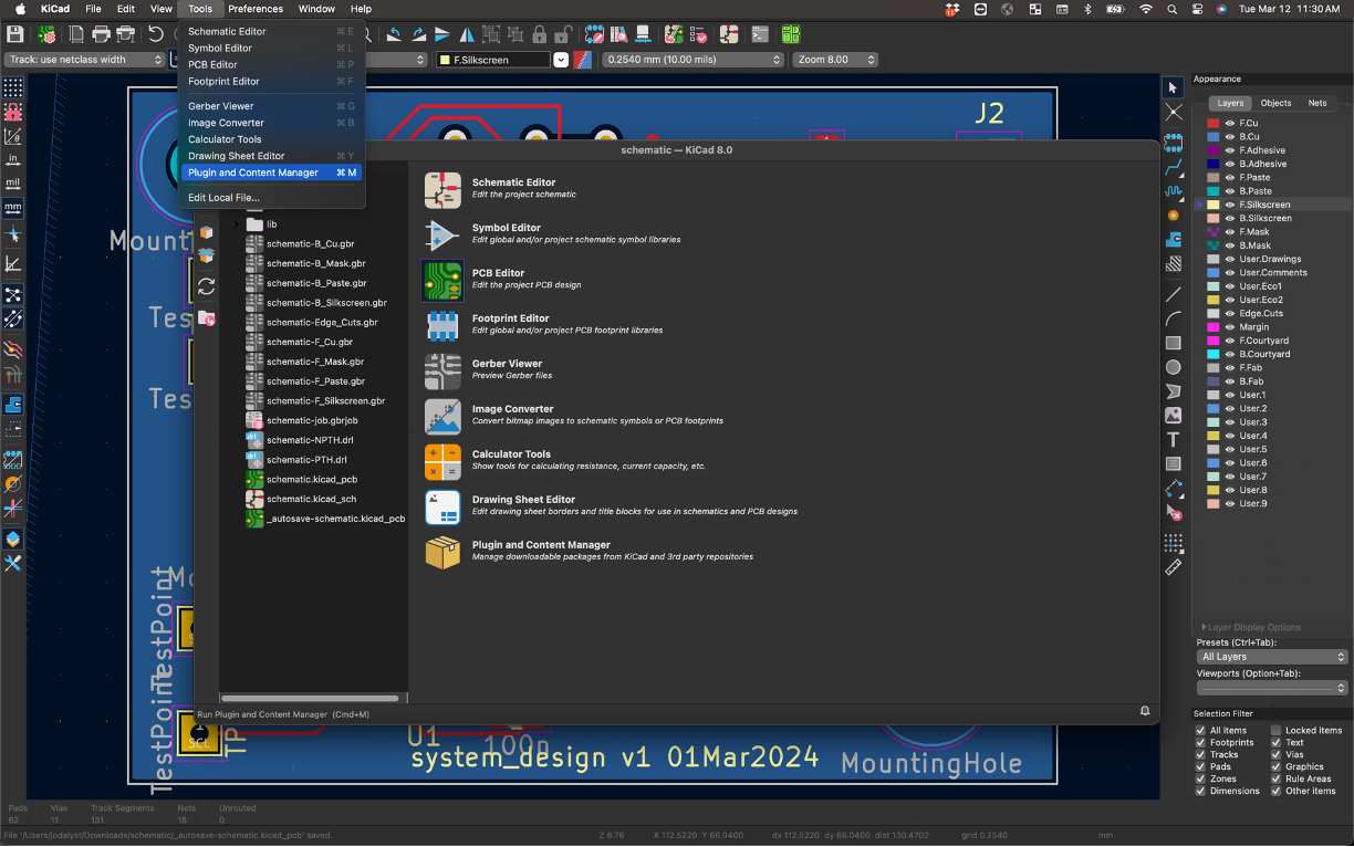
KiCad has a really neat plugin that can be activated which provides an easy-to-read "GUI" of your board and its components and elements. It can be very helpful in the assembly that you'll be doing. To install, first go into your main KiCad page and Tools -> Plugin and Content Manager.
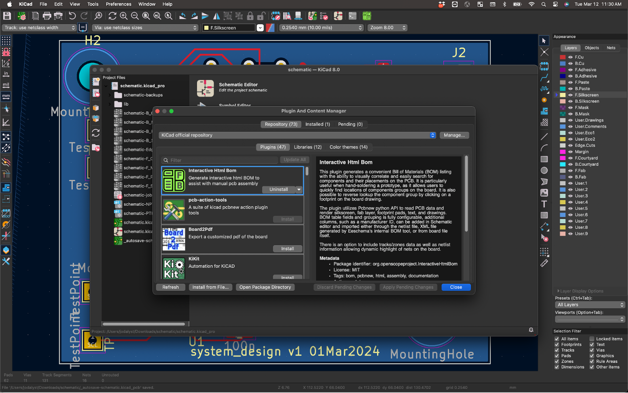
In there, look for the Interactive HTML BOM plugin. Install it.
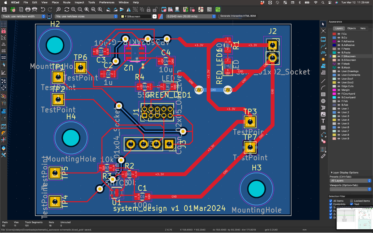
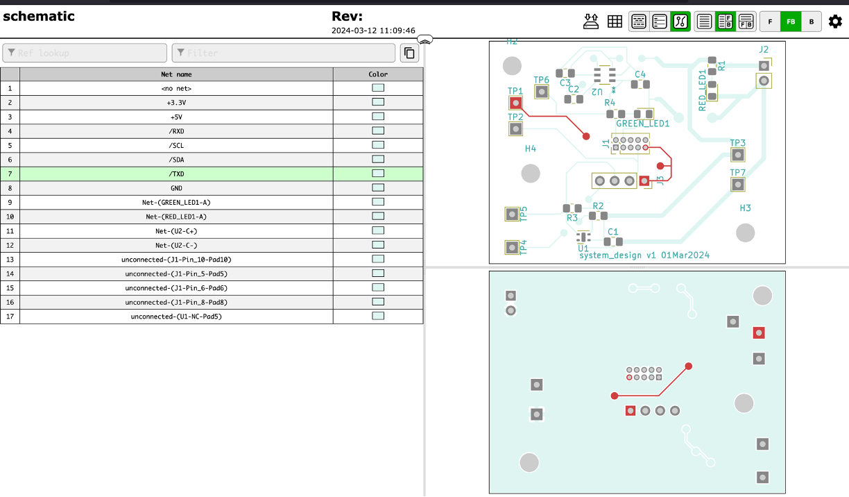
Once installed open up your PCB that you want to use with the plugin. In the top panel there should now be a bright-green button you can push corresponding to this plugin. Click it.
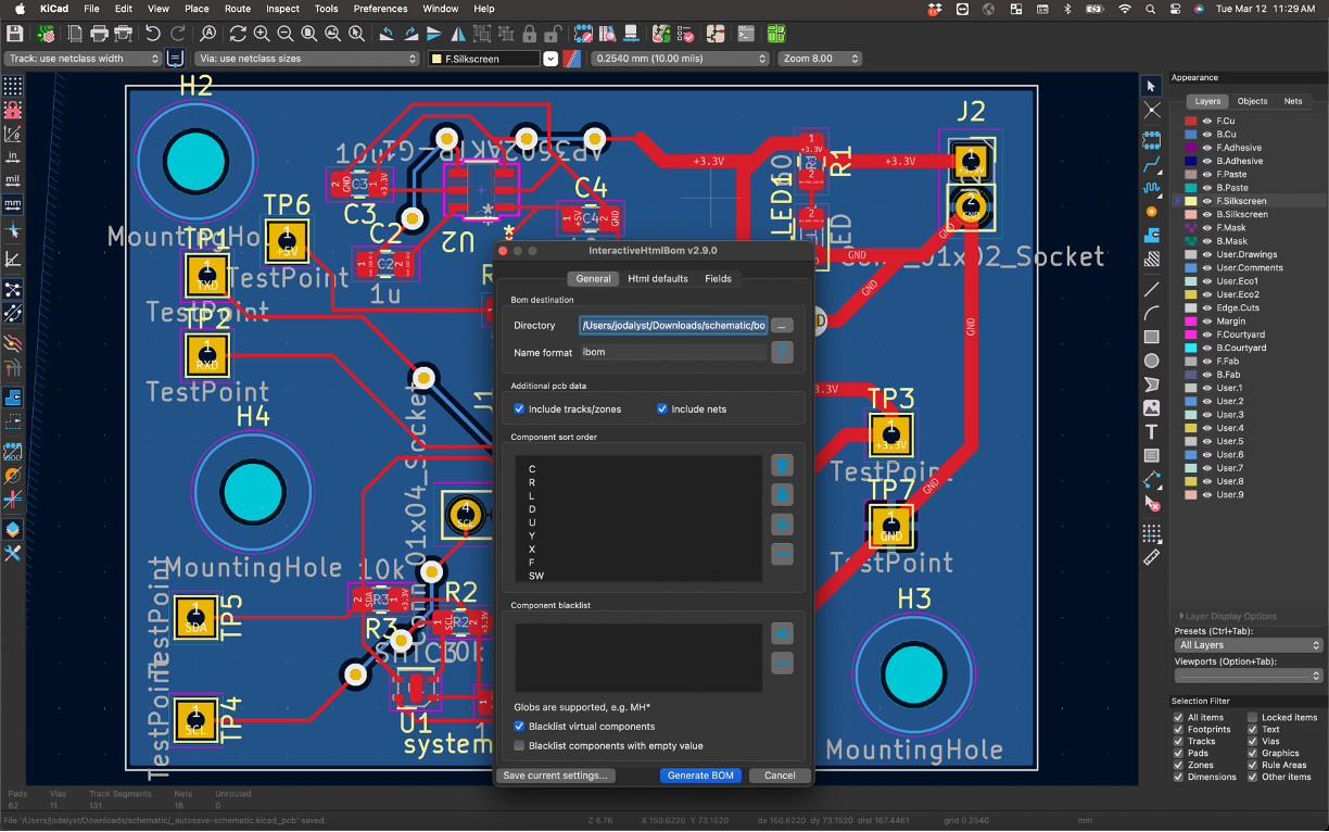
In the window that comes up, make sure to check the options about including nets and traces. When ready, then go and click Generate BOM.
You should be transferred to your web browser (hopefully it doesn't block this) and it'll present you with a web page that is your board along with all your components. There's different features you can look at including parts that need to be assembled:

As well as your traces and other angles of your board.
This tool can be really help when assembling since it will tell you what parts go where in a very easy-to-read and visualize manner.
Sensor board assembly
We have our sensor boards back! This is very cool -- these are designs you made and you laid out and you messed up (jk...hopefully). Right now we just have the boards themselves, so we'll need to solder components onto them to make them functional circuits. We've already had several rounds of board assembly and component soldering, so you are all pros.
Surface Mount Assembly
As we did for the LDO board in lab01, we're going to assemble the surface mount components first, then do the through hole component.
First, get the parts!
-
Mark down the values for the passives that you need from your KiCAD BOM. The passives (resistors and caps) are either laid out in the middle table in the 6.9000 parts organizer or in the reels of parts on the windowsills of EDS.
-
Cut and take only what you need! But before you cut, use a sharpie to label the section of reel, since they all look the same after you cut them! Some things like the resistors will have codes on them to read and figure out values, but the capacitors will basically be un-figure-outable. Get the LED from the staff table.
-
Get one FXLS8962 IC from the bin at the staff table. It's tiny. Do not lose it.
Apply Solder paste
-
The next step is to place a thin bit of solder paste on the exposed pads of the SMT components with a syringe, same as in lab01. The main difference is that our passives are a bit smaller (0805 vs 1206), so put down less paste.
-
The pads for the FXLS8962 IC are really close together. You won't be able to apply paste to each individual pad. So just smear a tiny bit of paste across the pads. As long as you don't put down too much, you'll be ok.
Feel free to ask the staff if you'd like a quick check on your paste job!
Place the parts
-
Place the Rs and Cs on the pads with tweezers. The orientation of the resistors and (non-polarized) capacitors does not matter for our board.
-
Place the LED. The LED does have an orientation. Most of our LEDs are from Broadcom (datasheet), but our green LEDs are from Lite-On (datasheet). They each have a line or mark denoting the cathode (negative) terminal. If you get the orientation wrong, it won't work!
-
Place the IC. Take care to orient the chip so that the pin 1 marker on the chip is aligned with the pin 1 marker on the silkscreen of your board. You can look at the chip datasheet to see where pin 1 is. Get the pads pretty well aligned with the pads on the PCB, even though the solder paste will smush around.
Reflow
- Place it on the hot plate and reflow, like you did in lab01. Remember that the reflow isn't complete until a bit after the smoke appears. You want to wait for the paste to get shiny and liquid and the parts to snap into position.
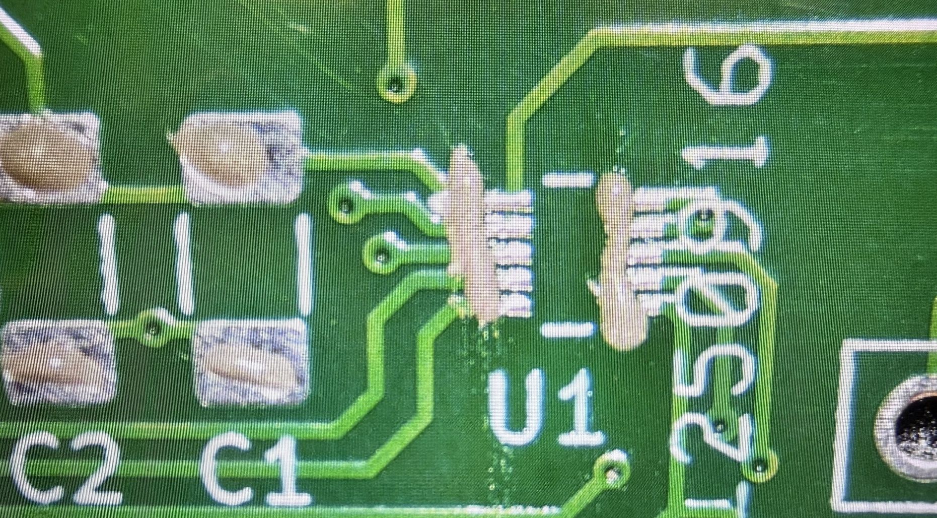
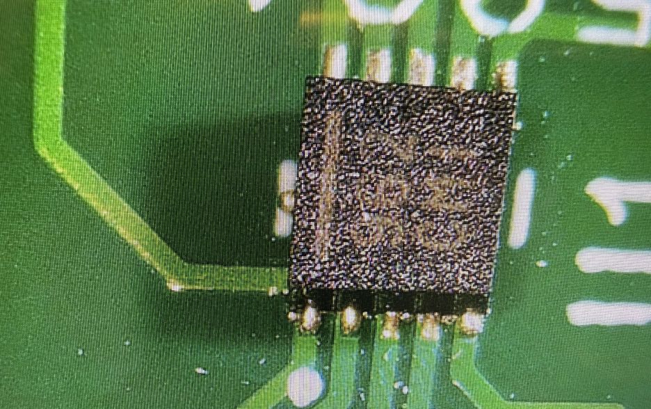
Inspect
- Before attaching the through-hole components, inspect your solder job under a microscope. In particular, look at the FXLS8962 pads at and angle and ensure that there are no solder bridges between pads.
-
A good way to tell if there are solder bridges is to probe adjacent pins. Take a look at your board layout. Pin 1 on the IC is VCC. Pin 2 is GND. Take a multimeter and probe those two nets (use convenient TPs, or connector pins, whatever), you should read either open or something fairly large, like ~MOhm. If you see just a few Ohms or less, you have a short. Then go probe between pins 2 and 3, pins 3 and 4, and so on.
-
If there are still solder bridges, you can go and try to reflow again. Or you can go to a soldering iron and suck up some of the solder with solder wick.
Thru-hole assembly
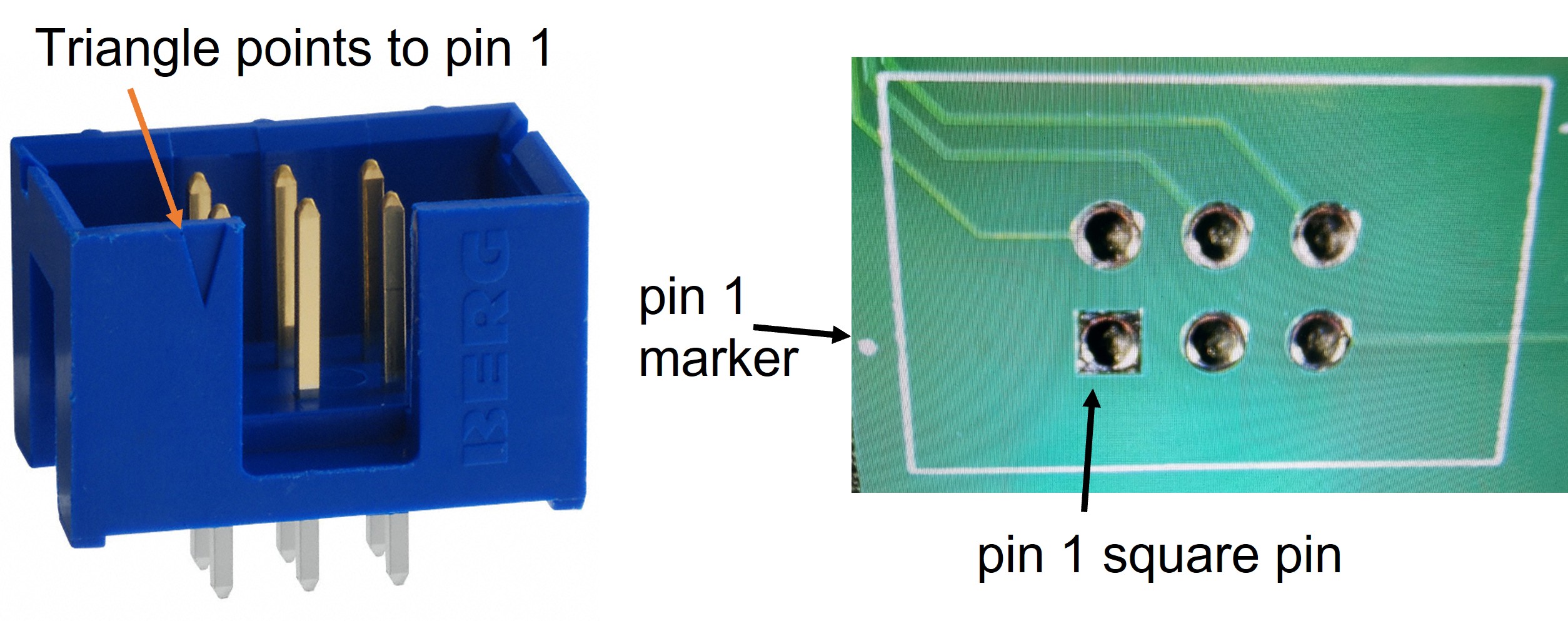
- Obtain a 2x3 IDC connector header and place it in your board in the correct orientation. Pin 1 on the connector should be oriented toward pin 1 on your PCB.
- Solder the connector header using a soldering iron.
Make a cable
In the last lab we made up some JST cables. In this lab we're going to show you a different style of cable. Specifically, we will make a 6-conductor ribbon cable using IDC (insulation displacement contact) connectors.
Ribbon cables with IDC connectors are neat because you don't have to peal the insulation -- the connector has little teeth that cut thru the insulation to make the connection. It's super fast.
Making Our Own Cables!
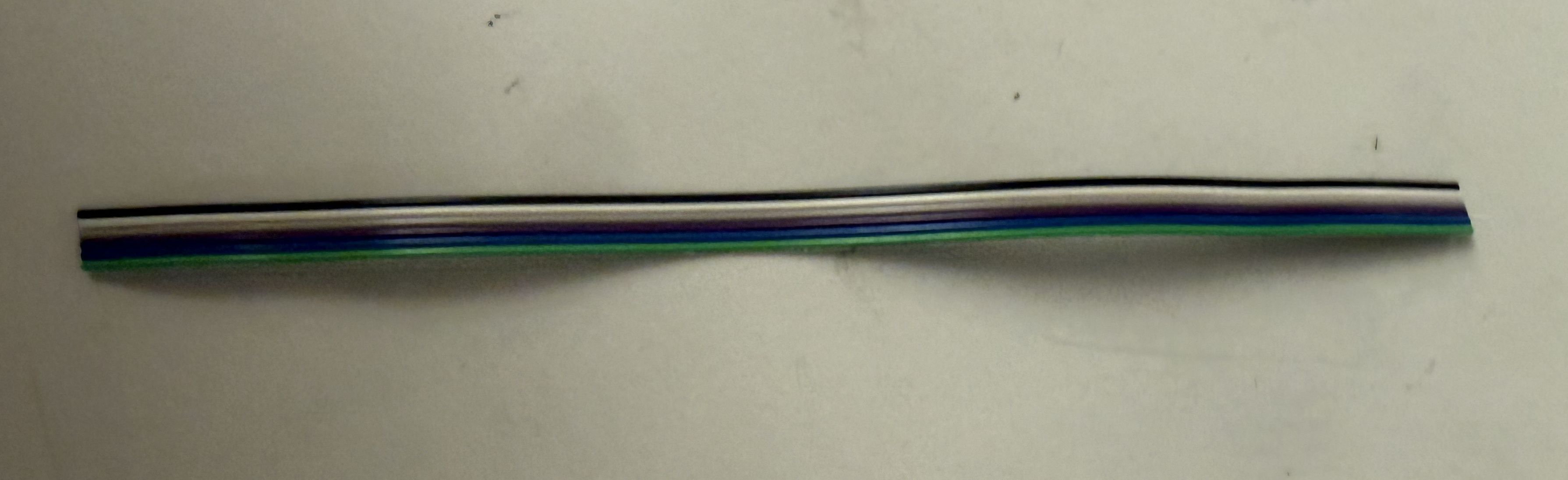
- Peel off 6 conductors from a ribbon cable and cut into a ~6" (15 cm) long segment. You can use the gray ribbon cable or the multicolored one. I like to use colors because it helps me keep track of orientation, but you do you.
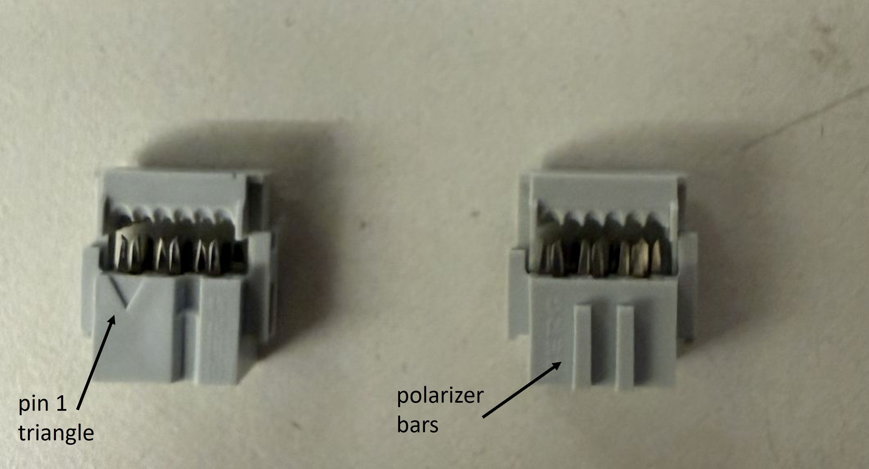
- Grab two 6-pin IDC connectors. We have two types. One has a little triangle indicating pin 1. The other has two little bars that polarize the connector, allowing the connector to fit into the housing in only one orientation. I prefer the latter as it prevents connection mistakes and frying my board.
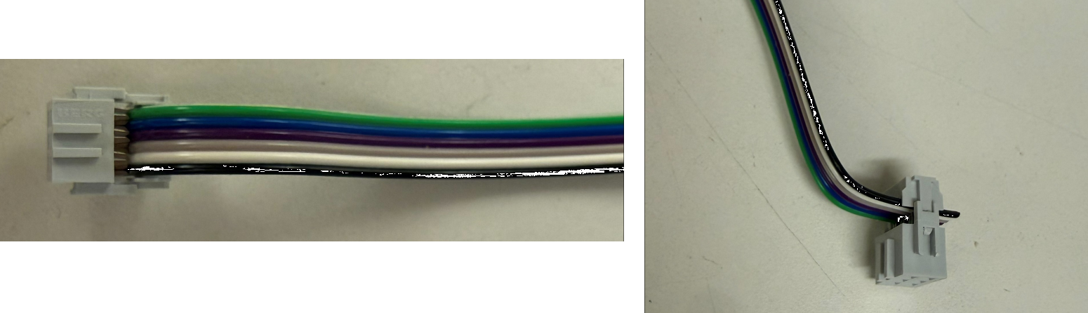
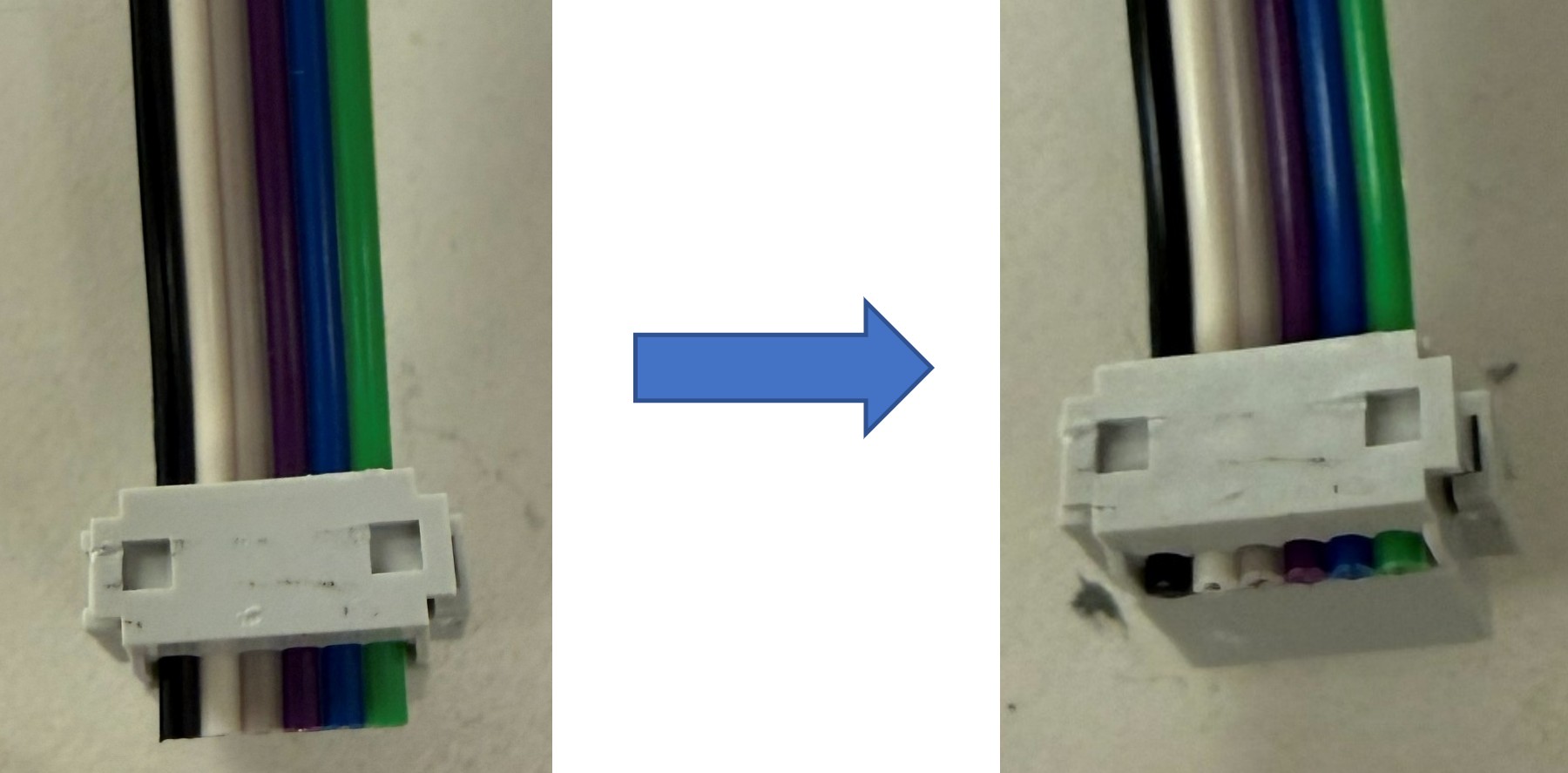
- Insert the cable into the opening of one connector, past the end, and keep it straight. Orient the cable & connector as shown in the image below. This orientation is ideally suited for the mainboard IDC connector housing.
- Clamp down on the connector to make close the contact. I like to use a set of pliers to do it. It's very satisfying.
- Now insert the second connector.
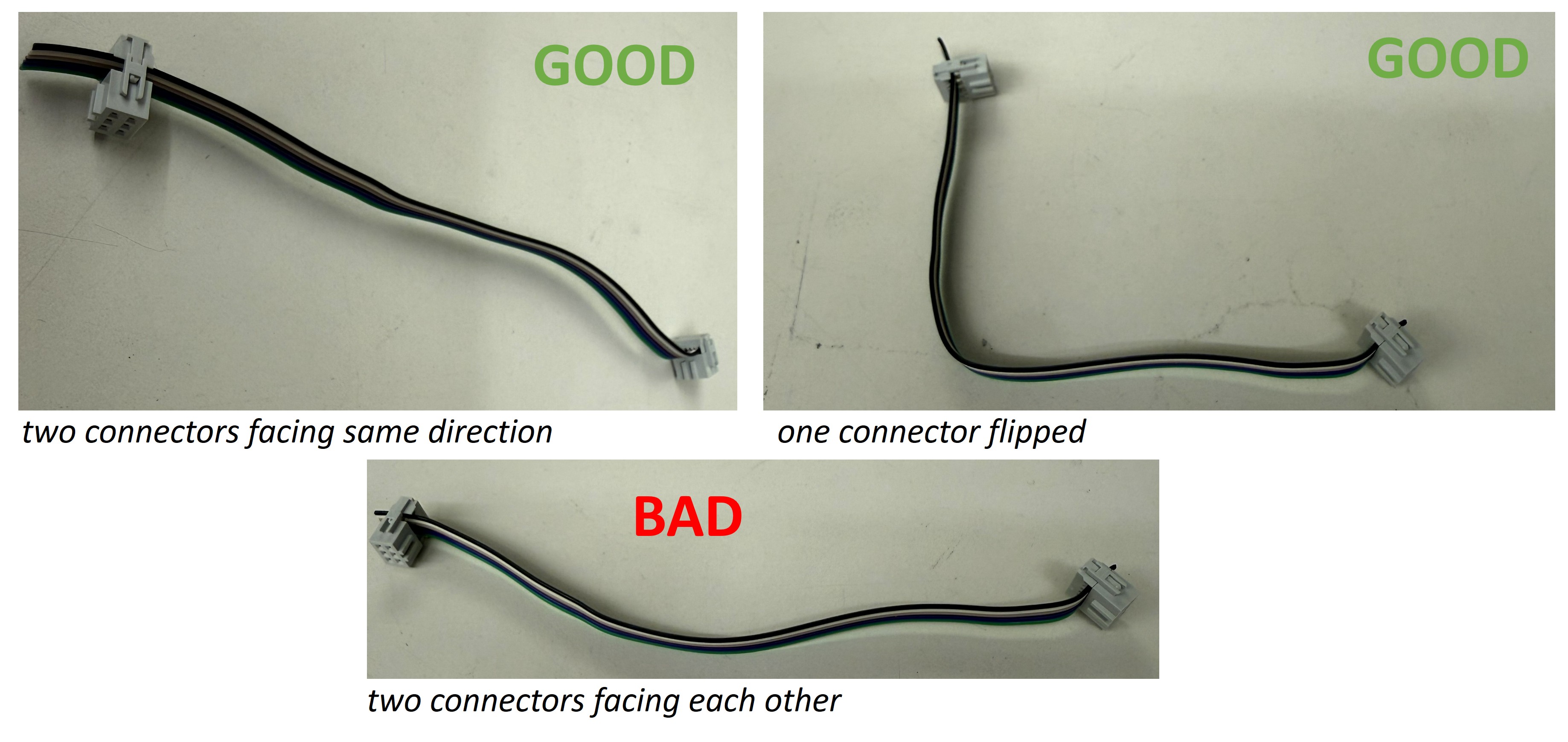
-
Double-check the orientation of the second connector. Now is your change to fix it if it's backwards.
-
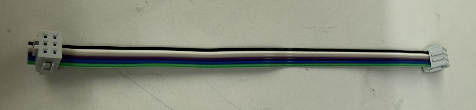
Clamp down on the second connector. When you're finished, your cable will look like so:
- Finally, because we are not animals, use a diagonal cutter to cut the overhanging cable bit flush with the connector.
Final assembly
Some soldering
Our 2x3 IDC connector has an SDA pin, and SCL pin, and an INT1 pin. We need to connect those to the appropriate pins on our ESP32C3. In the middle of your mainboard are little solder jumpers that allow you to connected SDA and SCL to IO3..7, and INT1 to IO0 or IO1.
-
For I2C, choose the same I2C pins as you've been using for your BH1750 board. Use a soldering iron and some solder to connect the relevant solder jumpers.
-
For IN1, choose a free pin, i.e., nothing should be connected to it on the breadboard. Solder the jumper for that pin.
Attachment and cabling
-
Attach the accelerometer board to the last remaining attachment post on your mainboard. By now you know how to do this: one (1) M3 screw and you should be good.
-
Attach the cable between the 2x3 IDC connector on your mainboard and the 2x3 IDC connector on your accelerometer board.
Add an LED
For the exercises that we'll undertake below, we'll need an LED.
- Find an LED in the lab (red is fine), and attach it and a suitable current-limiting resistor (~200 Ohm) to a free GPIO (I used GPIO4, but there are plenty of others) and your mini-breadboard.
Ask a staff member to look over your assembled board.

Testing
Proof of life
OK, let's run some code to see this accelerometer working.
-
Fire up VS Code.
-
Instantiate a new ESP-IDF project, set the target to esp32c3.
-
Unzip this fxls8974 library and place it into a
Componentsfolder in your project directory. -
Update the main
CMakeLists.txtto:
idf_component_register(SRCS "main.cpp"
                    INCLUDE_DIRS "."
                    REQUIRES fxls8974
                    PRIV_REQUIRES esp_driver_gpio)
- Replace your
main.cppwith the unzipped version of this code. Open it up and let's take a look.
// Initialize IMU with I2C configuration
if (!imu.begin(false, I2C_SCL, I2C_SDA)) {
    ESP_LOGE(TAG, "Failed to initialize FXLS8974");
    return;
}
Here we're initialize the accelerometer, using the I2C pins above.
// Proof of life!
ESP_LOGI(TAG, "FXLS8974 Product ID: 0x%02X", imu.getProductID());

// Set some acceleration parameters
imu.setFSR(2);
imu.setMagMode(1);
imu.setMode(1);
vTaskDelay(pdMS_TO_TICKS(10));  //tiny delay needed

AccelData accelData;    // instantiate data structure
Now our first method call, on getProductID. This is the one difference we've found between the FXLS8974 and the FXLS8962 that we are using -- they have different product IDs. No biggie.
Then we set some accelerometer parameters. setFSR sets the Full scale range in G's. So the max this accelerometer will measure in this setting is +/-2Gs. There are plenty of other settings. +/-2Gs is the most sensitive setting, but there are plenty of use cases where you don't want to be so sensitive, or you want to be able to measure larger accelerations (up to +/-16G for this part)
Then we setMagMode to 1, which causes the accelerometer to calculate the magnitude of the acceleration, in addition to the X-, Y-, and Z- components. So that we don't have to do floating-point math. Thanks, little dude.
Then is the important setMode method, which when set to 1 basically tells the IMU to get going and start measurements. We need a tiny delay afterward, but basically we're good to go.
accelData is a useful data structure to hold all the data from the IMU.
Finally, a while loop:
while(1) {
    if (imu.readAccelData(accelData) != 0) ESP_LOGW(TAG, "Data not ready");
    if (imu.readAccelMag(accelData) != 0)  ESP_LOGW(TAG, "Mag data not ready");

    ESP_LOGI(TAG, "Raw Accel: %d  %d  %d  %d",
            accelData.rawX, accelData.rawY, accelData.rawZ, accelData.rawMag);

    ESP_LOGI(TAG, "Accel: %.2f  %.2f  %.2f  %.2f",
            accelData.x, accelData.y, accelData.z, accelData.mag);

    vTaskDelay(pdMS_TO_TICKS(delayTime));
}
When we call the readAccelData and readAccelMag methods, we also check if the accelerometer has new data ready to read. This should rarely be an issue for our code, as the overall while loop is executing every 500 ms, much much slower than the accelerometer can measure (it's maximum data rate (also the default), called the "output data rate" is 3200 Hz). That said, I see occasional warning about the mag not being ready. Not a big deal.
Then we read the print the acceleration raw data (in bits) and the data in Gs.
- Build and flash the code and open the serial monitor. If everything worked, you should start to see accelerometer readings:
I (269) FXLS8974: FXLS8974 initialized successfully
I (269) IMU: FXLS8974 Product ID: 0x62
I (289) IMU: Raw Accel: -40  29  1020  1004
I (289) IMU: Accel: -0.04  0.03  1.00  0.98
I (789) IMU: Raw Accel: -40  20  984  992
I (789) IMU: Accel: -0.04  0.02  0.96  0.97
I (1289) IMU: Raw Accel: -40  49  1004  997
I (1289) IMU: Accel: -0.04  0.05  0.98  0.97
I (1789) IMU: Raw Accel: -16  8  1008  962
I (1789) IMU: Accel: -0.02  0.01  0.98  0.94
Make sure you understand all these numbers! The datasheet can help explain.
When you get things working, find a staff member and allow them to join you in celebration of your first working PCB! Then explain what all those numbers mean.
Build a tilt detector, the hard way
One common use case for an accelerometer in the semester projects is to tell if the sensor node has tipped over. We can figure this out from the accelerometer readings, because gravity always points down, and the if your IMU is horizontal, then down is along the Z-axis of the chip. '' Throughout the next set of exercises, we want to evaluate different ways of detecting tilt, and in particular issues of latency. The LED will help us assess latency.
In our first approach to sensing tilt, write a function that returns true if the accelerometer orientation (and hence the mainboard) has tilted at least 45 degrees from horizontal.
bool isTilted(AccelData current) {

}
Now, insert that code into this slightly modified version of main.cpp (or create a new project if you prefer to keep the old code around).
You may need to update the ledPin variable depending on what you used for your LED.
In this code, when the isTilted function returns true, the code prints a message to the serial monitor and turns on the LED. The LED then turns OFF after a delay given by delayTime, which is currently 1000 ms. If the device is still tiled the next time through the loop, the LED will get turned back on. And so on.
Build, flash, and open the serial monitor. Now, if you did it correctly, the ESP32C3 should report if you tilt the mainboard and the LED should turn ON when that occurs. Try it and make sure it works when you tilt in various directions.
There are a few limitations of this approach. First, it assumes that the device was set up to be perfectly horizontal to begin with. It would be a bit smarter to take an initial reading of the angle and then check whether that angle changes substantially.
There are three bigger issues, though. First, we are detecting tilt via polling, meaning we keep looping and checking, which means the processor is always working, wasting power. Second, notice that there can be a delay between when you tilt and when the LED turns ON. This is due to the 1000 ms delay that we've inserted into our loop. Third, we are not taking full advantage of the IMU's capability, because, as it turns out, the IMU has an innate ability to detect tilt directly.
Build a tilt detector, a somewhat better way
The FXLS8974 (or, ok, the FXLS8962) has a built-in orientation detection subsystem. You can tell it exactly how much of an orientation change you'd like to detect (the default is 45 degrees) and it will set a register bit if that change occurs. It's very nice.
To use the orientation detection feature, we need to set bits across a few registers. Luckily for you, our library makes that easy.
If you add the following lines to the beginning your app_main where you configure the IMU:
imu.orientEnableDbcn(1);
imu.setorientDbCount(100);
imu.orientEnable(1);
The first two lines enable a debouncer, meaning that the orientation detection will only fire if the orientation persists for a period of time, in this case for 100 readings (which, at 3200 Hz, is around 31 ms). Then the last line turns on the orientation detection.
You'll also want to initialize an instance of the OrientData data structure (and you can get rid of the AccelData one, which we don't need anymore):
OrientData orient;
The key method call is getOrientation. Take a look at the library code for this method in fxls8974.cpp. Like many other methods in the library, we are either getting a register value or setting a register value.
In this case, what is the name of the variable corresponding to the register we are reading?
And what is the name of the corresponding register as per the data sheet?
We next set a bunch of OrientData structure variables using various bitmasks.
Which bit is read to update the NewOrient variable?
Look through the datasheet to make sure you understand what that bit corresponds to. Also read and make sure you understand the other bits in that register (LO, LAPO, BAFRO). Basically, the internal computation of the IMU enables us to measure and read-out various types of orientation changes. It's pretty powerful.
Create a new ESP-IDF project. Within that project, write a new variant of your code that:
- Uses the
getOrientationmethod to detect tilt using polling - Writes the message "Orientation change detected!" and the new orientation upon detecting an orientation change, using the ESP_LOG library
- If there is no orientation change, it does not print anything
- Set the
delayTimeto around 50 ms to make the system more responsive
This code improves on our first version because we're using the IMU's on-board orientation detection, offloading floating point math from the MCU. In addition, now the LED will not stay ON if we're tilted. It turns ON during any change in orientation, which is pretty cool. However, we are still polling, and there is still substantial latency between tilting and the LED turning ON.
Show your two tilt detector pieces of code working, and explain how they work.
Postscript: Luke, there is another
It turns we can do even better than this, and in the next problem set we'll do that. Stay tuned.