Lab 1
Please Log In for full access to the web site.
Note that this link will take you to an external site (https://shimmer.mit.edu) to authenticate, and then you will be redirected back to this page.
Before you leave, it's very important to get into the habit of leaving the lab space ready for the next person. So important that we will have future checkoffs specifically for this purpose.
Steps for cleanup:
- Carefully pick up your system and place into a yellow paper envelope.
- Please return the tools (wire strippers, etc.) to staff table.
- Throw away loose wires in your work area.
- Throw away paper, food, etc. in your work area.
Getting Started
You should have already installed the software toolchain on your laptop. If you haven't, please do so now from our software install page.
Assembling the embedded system
Today we'll hook up the initial elements of the system.
We're using a custom 6.900-specific board. It's is mostly ready to go, but not quite.
Get the relevant parts from the stash in the middle of the room:
- ESP32C3 microcontroller Mainboard
- Li-ion 18650 battery
- (3) 2-pin jumpers
- 6.900 backplane
- (3) M3 x 6-mm screws
- USB-C cable
- mini-breadboard
- LDO board
- AP7363-33D LDO chip
- (2) 10 uF 1206 capacitors
- Right-angle 1x3 female header
- BH1750 breakout board
You'll want access to the datasheets, pinouts, and so on for the parts while you do this lab:
- 6.900 ESP32-C3 Mainboard schematic, layout
- ESP32-C3 datasheet
- LDO board schematic, layout
- AP7363-33D LDO datasheet
- BH1750 datasheet
Let's do some soldering
LDO board
We'll usually power our system with a Li-Ion battery or the USB connector. These are either at ~3.7 V (battery) or 5.2 V (USB). However, the rest of our system wants 3.3 V, so we will use a regulator to turn that unregulated input voltage into 3.3 V.
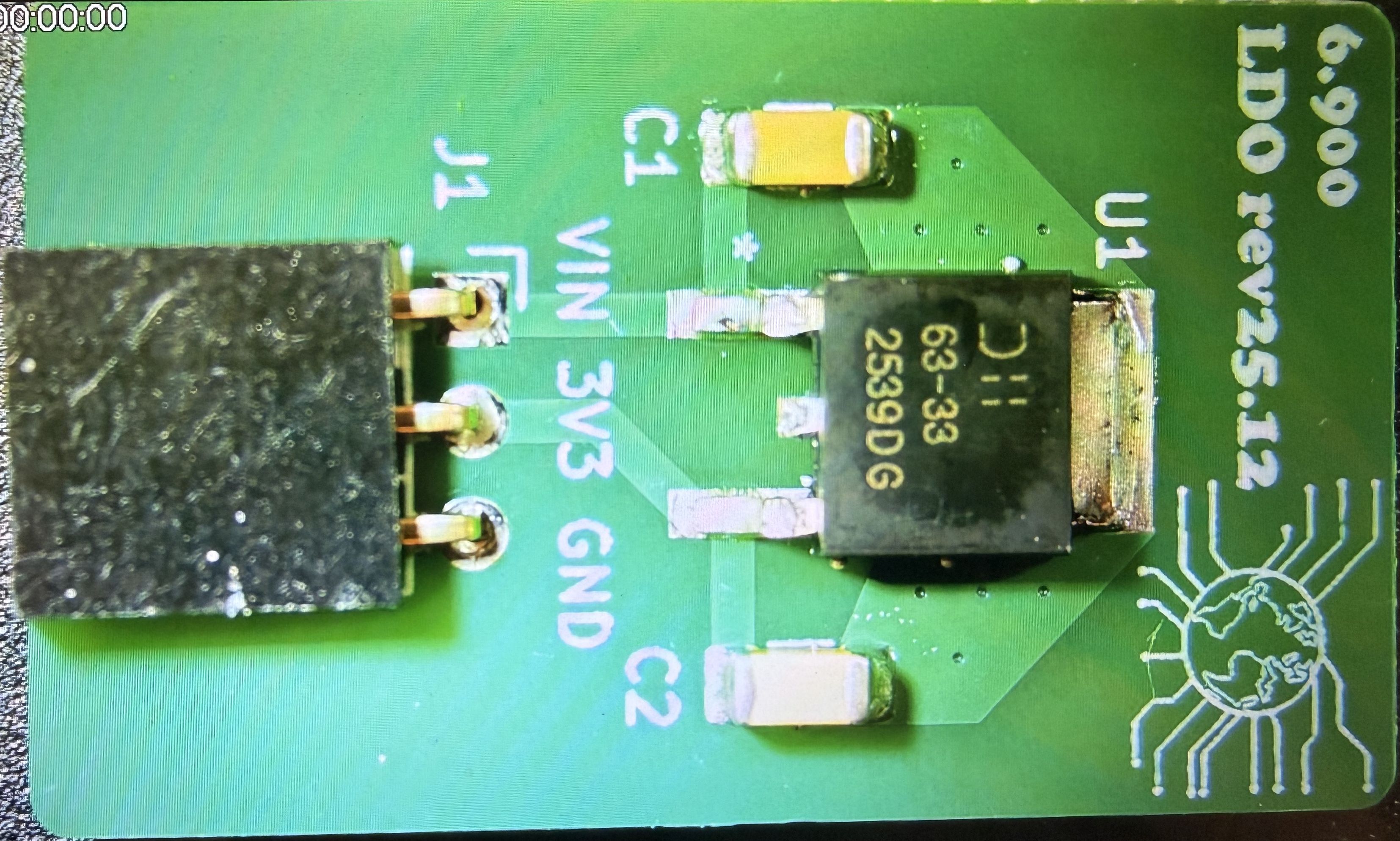
That's the little board you have that is labeled "LDO rev25.12". LDO is a low-dropout voltage regulator. It takes a varying input voltage and outputs a constant well-defined voltage for the rest of the circuit. Since our ESP32C3 and peripherals run on 3.3V, that's what we want to create. And lo and behond, our AP7363-33D chip does just that (maybe you can guess now what that -33D suffix means).
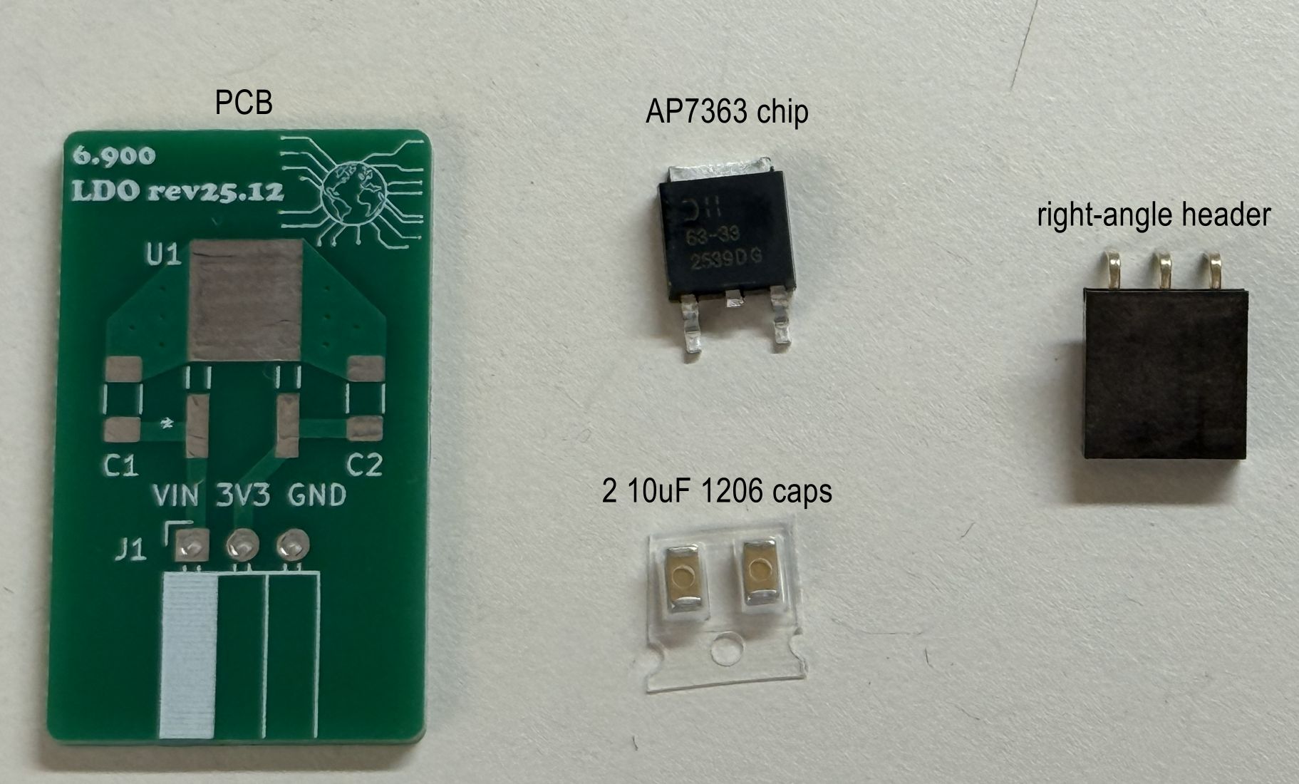
You will have to solder up that board, though. It's pretty straightforward, with four components: the AP7363 chip, a three-pin right-angle female header, and two 10 uF capacitors.
Safety
There are a few hazards in soldering:
- Hot Stuff: The hot plate and soldering iron are really hot, like moreso than Donna Summer's 1979 single. Lead-free solder melts at around 220°C (~420 °F). As a result, the soldering iron and hot plate have to be at least that temperature, so be careful to not burn yourself! If you drop a soldering iron just let it fall and get out of the way, resist the urge to catch it.
Also be sure to wear safety glasses - no need to go blind because you get some hot beads of solder flicked into your eyes.
- Solder Paste: We'll be using solder paste today to solder our tiny surface mount components. It's super cool and easy to use, but it's easy to get everywhere. We recommend that you wear gloves when handling the paste.
Technique
We'll be using two methods to assemble our LDO board - one for the surface-mount components, and one for the right-angle through-hole connector. You may have done some through-hole soldering in the past...but the surface-mount will be newer for many of you. We'll solder the surface mount parts first, then solder the through hole part.
Surface Mount Assembly
First, make sure you have the parts. This picture below shows what you need:
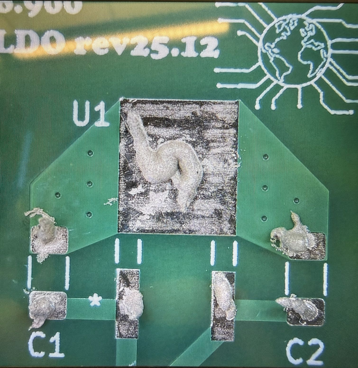
OK the next step is to place a thin bit of solder paste on the exposed pads of those components with a syringe. We don't want this layer to be super thick; otherwise, we may short pads by applying too much solder. If you do, you can simply use a paper towel to wipe off the excess. We also have some zipties in the 6.9000 parts drawer that can be used to easily scrape solder paste off the boards. It also doesn't need to be super precise.
Here's an image of the board after applying paste.
Feel free to ask the staff if you'd like a quick check on your paste job!
Place and Heat
Next, place the parts on the pads with tweezers. The orientation of the (non-polarized) capacitors does not matter for our board. When you place components with tweezers, it's good to push the parts into the paste a bit so they are embedded.
Now you need to heat up the solder. This video shows what will happen, in around 15-20 seconds or so:
So bring your board to the hotplate. It should already be set up, but if not, set the temperature to 250 C. This is a bit above the solder melt temperature, which is what we want.
Once your board is on the hotplate, it will start to smoke a bit, and in around 15-20 seconds or so, you'll see the solder do what it does in the video above. Once that occurs, carefully remove the board with the tweezers and gently place it on the bench. Don't jossle it, else the parts might get dislodged while the solder is still melted!
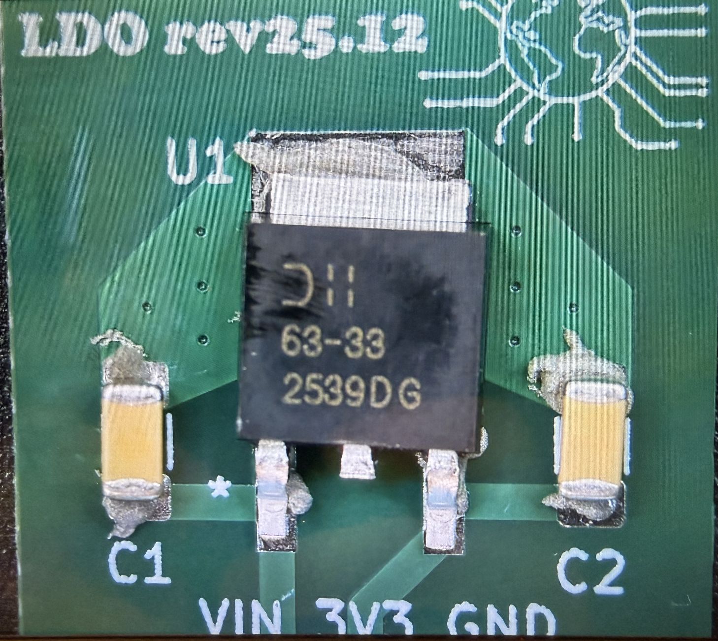
Here's an image of what it should look like after reflow:
Hand-solder the right-angle header
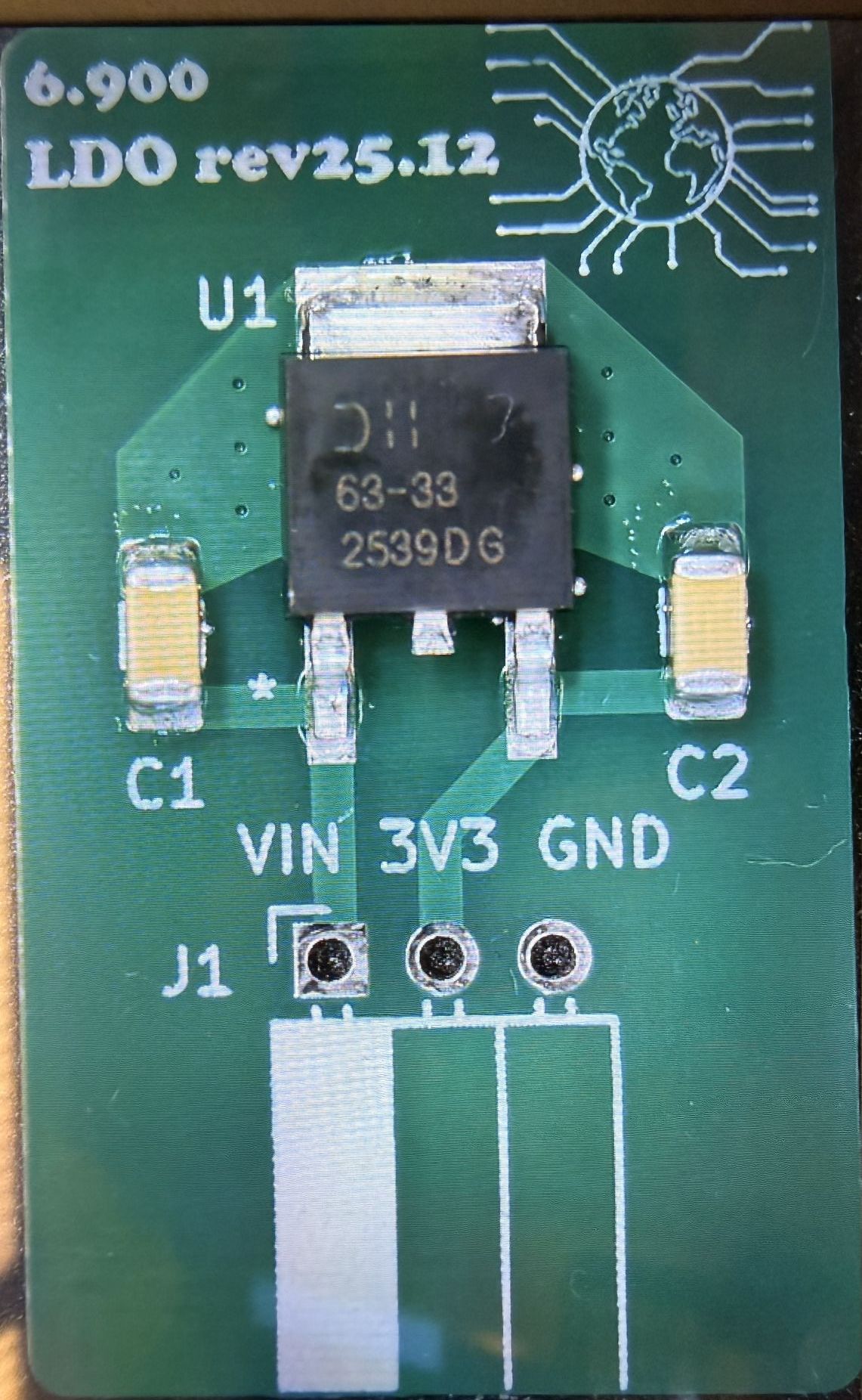
Finally, attach the right-angle header to the board and solder it from the back. You may want to add a little header or something to prop up the other side of the board so it all lays flat.
Here's an image of the board when it's all done:
Solder the BH1750 board header
The other bit of soldering we have to do is to solder the 5-pin header strip to the BH1750 board. Go ahead and do that.
And now for some mechanical assembly
To secure your embedded system and make everything as nice as possible, we're going to attach it to a backplane. This will also give you examples of how to attach your project PCBs to your enclosure.
Today we're going to use screws that will tap into aligned holes on the backplane. Basically, we've designd the 3D-printed backplane so that it has holes that align with the 3 holes drilled into the PCB. The holes are sized so that when you screw M3 screws into them, they will cut threads into the plastic (so-called "tapping"). This assembly technique is not great if you want to repeatedly attach/detach a board, but for one-time (or two-time) assembly it's quick and easy.
-
Take the mini-breadboad and attach it to the mainboard header pins.
-
Align the top-left screw hole on the PCB with the screw-hole on the backplane, and screw in the M3 screw. You will need to apply pressure and go slow to cut the threads. Leave it a bit loose -- do not tighten fully.
-
Next repeat with the bottom-left screw. Again, do not tighten fully.
-
Next, tilt up the mainboard/breadboard and pull off the adhesive liner on the back of the breadboard.
-
Press the breadboard down onto the backplane to attach.
-
Screw in the central screw. Tighten hand-tight.
-
Finally, tighten the two left screws hand-tight.
Add the 6.900 mainboard jumpers
For today's lab, you are going to power your system from the LiPo battery. So go ahead and insert it into your mainboard. It's a tight fit, but you can get it in there. Be aware of the orientiation! The "button" on the battery goes to the left (+ terminal).
Now, with the battery installed, you might be wondering why the mainboard isn't "ON". If we take a look at the circuit schematic, we can see why. You can look at the entire schematic linked above, but here we've zoomed in on the two relevant regions.
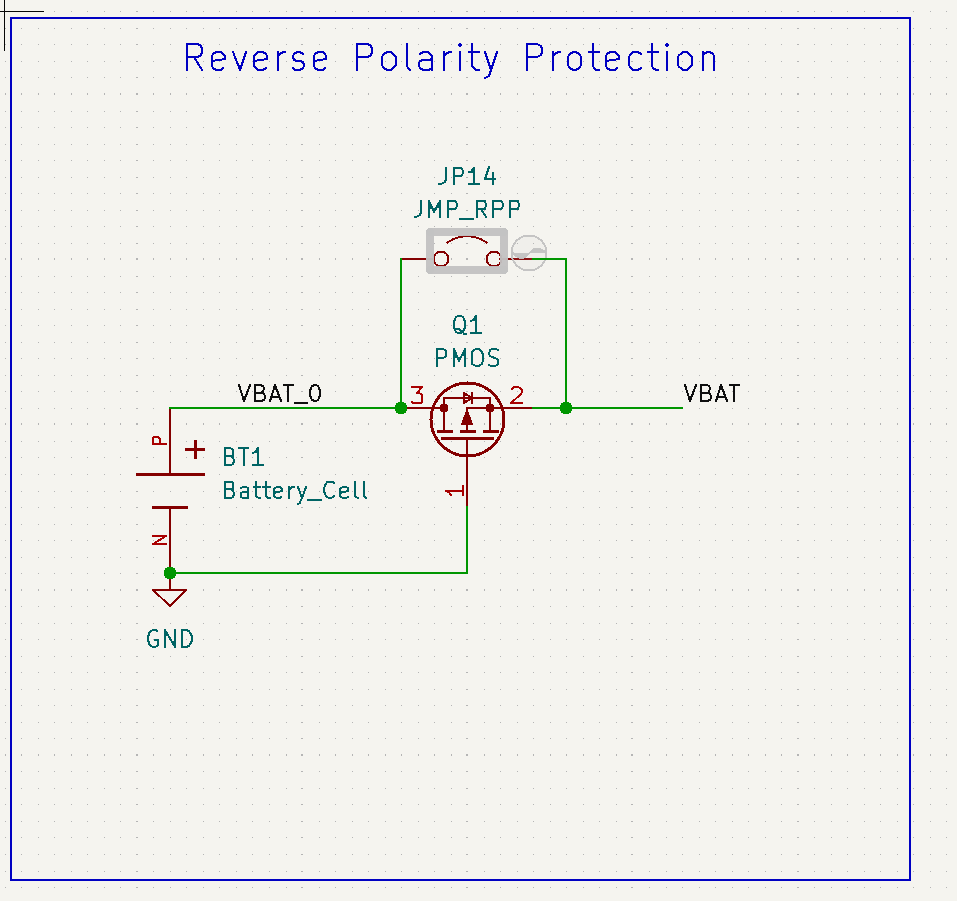
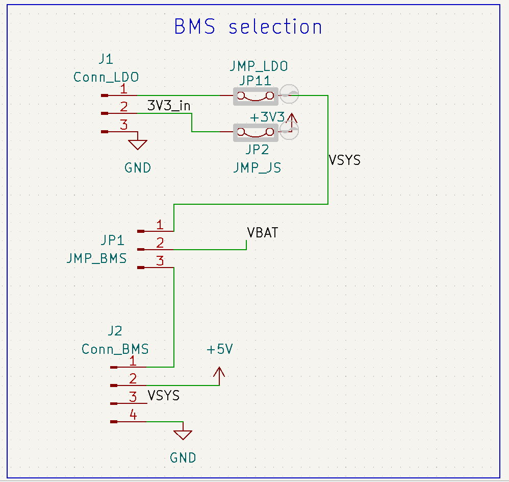
In the first schematic, you can see that positive lead of BT1 (the battery) is connected to the Q1 PMOS transistor, and then becomes VBAT, and in the second schematic you can see that VBAT connects to JP1, which is a jumper. It allows us to choose to connect the battery directly to the LDO (Conn_LDO) or to a battery manager (Conn_BMS). Today we want to connect the battery directly to the LDO, so we need to bridge that jumper.
Find JP1 on the pcb layout. You want to add a jumnper between the input (middle) pin and the "No BMS" pin, since we're not using a BMS today.
There are two more jumpers that you need to add, to JP2 and JP11. Those close the circuit so that the power from the battery can flow to the LDO and then to the rest of the system. Add those. Your mainboard should now have three jumpers on it.
Assemble the starter system
Hook up the ESP32 + LDO + BH1750
Next let's finish hooking up the boards.
The LDO board gets attached to the ESP32C3 mainboard via the REG connector. Insert the LDO board with the components facing up!
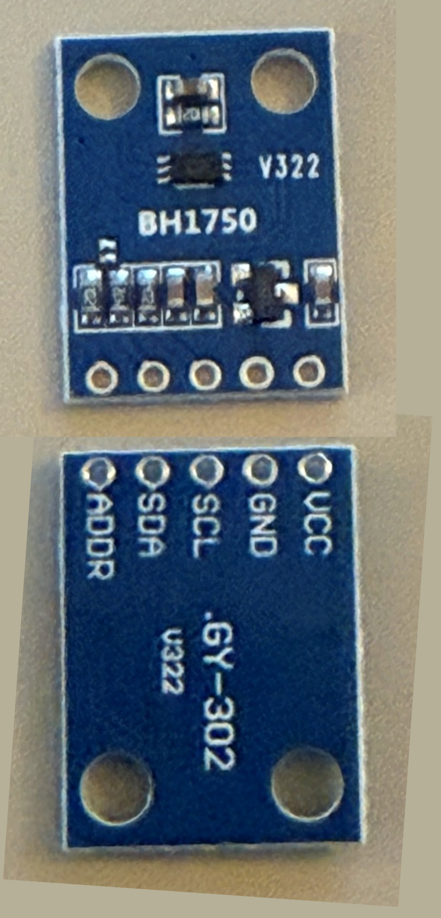
As a fun sensor to use for this first lab, we've chose a BH1750 light sensor. This sensor outputs a digital value proportional to the ambient light. You know how your phone screen gets brighter in the sun, or how your map software turns to dark mode when it's, um, dark out? Well, they use a similar sensor to do that.
Attach the BH1750 breakout board to the mini-breadboard using its header. Cause it's hard to remember what the pins are since they are labeled on the back of the board, here's a pic to help you out.
Wire up 3V3 and ground.
The other two connections to make are the SDA and SCL connections for the I2C communications bus. While you can choose most of the ESP32C3 GPIOs for these signals, we recommend choosing GPIO4 thru GPIO7 -- one for SDA, one for SCL.
When you make your connections, please keep your wires flat, neat, and short. Use color coding for ground, 3V3, signals, etc.
Show your wired-up system to a staff member.

Getting some code running
Start a new ESP-IDF project in VS Code
Now let's actually get something running on our microcontroller to see if our software is working.
In Visual Studio Code:
-
Navigate to View > Command Palette.
-
Type ESP-IDF: New Project and select the command to launch the New Project wizard.
-
Wait a bit. At some point, near the top of the windows you'll see a box asking which ESP-IDF framework to use. Click the box to select the default (ESP-IDF v5.5.1 or similar).
-
Now you'll see the New Project dialogue wizard.
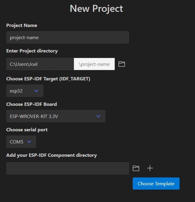
Enter a project name, like lab01, and select a suitable Project directory to use.
-
For "ESP-IDF Target", select "esp32c3".
-
For "ESP-IDF Board", select "ESP32-C3 chip (via builtin USB-JTAG)"
-
It should auto-select the right serial port.
-
Now select "Choose Template" and on the next screen under "ESP-iDF Templates" choose "sample_project", which is basically a blank app.
-
Now select "Create project using template template-app"
And now again we wait a bit while it does some stuff.
- At some point, you'll see a little window pop up asking if you want to open the project: Hit "Yes".
ESP-IDF project organization
For this very simple project, you can see that we have the following directory structure:
- lab01/
    - CMakeLists.txt
    - main/       - CMakeLists.txt
                  - main.c
There are some other files but these are the main ones. main.c is our program code. The two CMakeLists.txt files direct the compilation process.
One important thing to change is that we want to run a C++ file, not just C. To do that:
-
rename
main.ctomain.cppby right-clickng onmain.cppin the VS Code Explorer. -
If you do that and then navigate to the
CMakeLists.txtfile in the\maindirectory, you'll see it automatically updated theidf_component_register...line. -
If you rename via the command line or elsewhere, you'll need to manually update
CMakeLists.txt. Not a big deal.
main.cpp, where your program lives
Now select main.cpp in VS Code. It's a short stub right now:
#include <stdio.h>

void app_main(void)
{

}
app_main is the main function that runs.
Since main.cpp is a C++ file, but ESP-IDF expects C code, we need to add an extern statement bracketing app_main. And then let's put in a short, simple program just to get things going.
#include <stdio.h>
#include "freertos/FreeRTOS.h"
#include "freertos/task.h"
#include <esp_system.h>

extern "C" {
void app_main(void)
{
  while(1) {
    printf("Hello World\n");
    vTaskDelay(pdMS_TO_TICKS(1000));
  }
}
}
We've added a few #includes to bring in some of the libraries that ESP-IDF needs to run.
Beyond that, there are only three statements to this code:
while(1) {
This line makes sure we repeat this code block forever.
printf("Hello World\n");
Prints Hello World (with newline). Where does it print to? ESP-IDF automatically sets up the serial port as the default endpoint to print to.
vTaskDelay(pdMS_TO_TICKS(1000));
This line adds in a 1000 ms delay. the pdMS_TO_TICKS macro converts the argument from milliseconds into clock cycles, while vTaskDelay is the ESP-IDF delay function.
delay function, vTaskDelay is non-blocking.Build the project
Let's "use" this code. First, we need to build the code.
At the bottom fo the VS code window is a "Build Project" icon. Hit that.
If you run into issues using the build button at the bottom or are using the command line instead of the VS code extension, you can instead open an ESP-IDF terminal and run idf.py build or use Ctrl/CMD+E, B.
Now VS Code will proceed to build the project. It can take a while the first time. Patience.
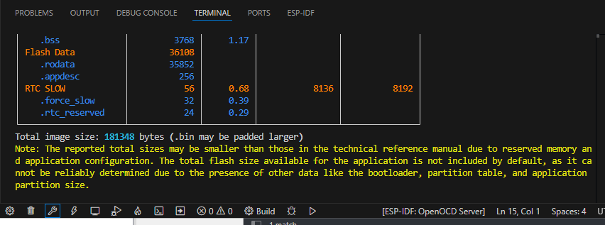
Various useful information will pass by, ending with a colorful table showing you how big your code is.
If you get no errors, then let's upload.
Upload/flash the project
Next, making sure that you have physically connected your ESP32 to your computer, select the ESP-IDF:Build, Upload, and Monitor icon at the bottom of the VS Code window. You can also run idf.py flash followed by idf.py monitor in the ESP-IDF terminal.
Again, it will build. After a bit, a message at the top of the Visual Studio Code window will ask you to "Select the flash method...". Select "UART", since we are using the serial port to upload the code.
Then after a few moments, the screen will change and you should see messages indicating it is uploading the code to your ESP32C3.
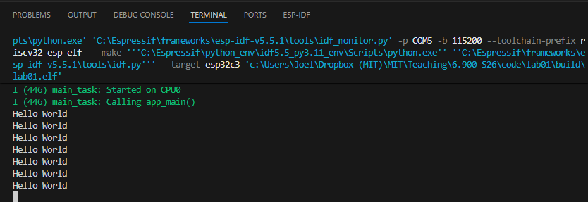
Serial monitor
The code above should be printing to the serial monitor. You should see Hello World printed over and over.
Let there be light
Incorporating the BH1750 component
OK, now that we have our Hello World out of the way, let's do something more interesting -- let's sense light levels.
Rather than write our own I2C library to interface with the BH1750, we're going to use a pre-written one by Espressif. In the Espressif ecosystem, they use the term "component" for what we would refer to as a "library", basically a set of files (.c, .h) and the associated CMakeLists.txt for you to use peripherals, etc.
To use the library, in VS Code:
-
Navigate to View > Command Palette.
-
Type ESP-IDF: Show ESP Component Registry.
-
In the UI that launches, search for "BH1750".
-
Select the "espressif/bh1750" component.
-
On the next screen, select "Install".
If you are using the command line instead, run idf.py add-dependency espressif/bh1750
This will bring in the bh1750 component, which is not part of the core ESP-IDF system. You'll now see a new directoy "managed_components" in your project directory, and some new files.
Examine our new project code
Now, let's get some basic measurement code running. Copy/paste the following into your main.cpp:
#include <stdio.h>
#include "freertos/FreeRTOS.h" // ESP32 RTOS
#include "freertos/task.h"
#include <esp_system.h>
#include "esp_log.h"

#include "driver/i2c_master.h"   // I2C driver
#include "bh1750.h"              // espressif/bh1750 component


// I2C definitions
#define BH1750_ADDR     0x23    // BH1750 default I2C address
gpio_num_t sda = GPIO_NUM_4;
gpio_num_t scl = GPIO_NUM_5;

static const char *TAG = "LAB01";

extern "C" {
void app_main(void)
{
    // Create I2C master bus
    i2c_master_bus_handle_t bus = NULL;
    i2c_master_bus_config_t bus_cfg = {};
    bus_cfg.i2c_port = -1;      // ESP32C3 only has one I2C port
    bus_cfg.sda_io_num = sda;
    bus_cfg.scl_io_num = scl;
    bus_cfg.clk_source = I2C_CLK_SRC_DEFAULT;
    ESP_ERROR_CHECK(i2c_new_master_bus(&bus_cfg, &bus));

    // Create BH1750 device on the bus
    bh1750_handle_t bh = NULL;
    ESP_ERROR_CHECK(bh1750_create(bus, BH1750_ADDR, &bh));

    // Power on and set measurement mode (continuous, 1 lx resolution)
    ESP_ERROR_CHECK(bh1750_power_on(bh));
    ESP_ERROR_CHECK(bh1750_set_measure_mode(bh, BH1750_CONTINUE_1LX_RES));

    // Log message
    ESP_LOGI(TAG, "BH1750 initialized at addr 0x%02X; reading lux every 1s...", BH1750_ADDR);


  while(1) {
        float lux = 0;
        esp_err_t err = bh1750_get_data(bh, &lux);
        if (err == ESP_OK) {
            printf("Ambient light: %.2f lux\n", lux);
        } else {
            ESP_LOGE(TAG, "bh1750_get_data failed: %s", esp_err_to_name(err));
        }
        vTaskDelay(pdMS_TO_TICKS(1000));
    }
}
}
This code is obviously a bit more elaborate than what we had earlier. Let's take a look at a few parts:
    // Create I2C master bus
    i2c_master_bus_handle_t bus = NULL;
    i2c_master_bus_config_t bus_cfg = {};
    bus_cfg.i2c_port = -1;      // ESP32C3 only has one I2C port
    bus_cfg.sda_io_num = sda;
    bus_cfg.scl_io_num = scl;
    bus_cfg.clk_source = I2C_CLK_SRC_DEFAULT;
    ESP_ERROR_CHECK(i2c_new_master_bus(&bus_cfg, &bus));

    // Create BH1750 device on the bus
    bh1750_handle_t bh = NULL;
    ESP_ERROR_CHECK(bh1750_create(bus, BH1750_ADDR, &bh));
This section sets up the I2C peripheral and the BH1750 object. There are more parameters one can set on the bus_cfg struct, but here we try to be somewhat minimalist.
You'll also notice the ESP_ERROR_CHECK macros encapsulating many of the statements we run. Espressif writes many of their functions so that they return error codes, described in detail in their docs. If the function returns without error, the return code is ESP_OK, which is just an enum for zero.
ESP_ERROR_CHECK is a macro that reads the returned error codes and if it's not ESP_OK, prints an error message to the serial port.
You don't need to encapsulate all these statements in ESP_ERROR_CHECK, but having these extra checks helps in debugging.
ESP_LOGI(TAG, "BH1750 initialized at addr 0x%02X; reading lux every 1s...", BH1750_ADDR);
This statement shows our first use of the ESP Logging Library. This is a pretty powerful logging library that you'll want to use in your projects.
Each log message has an associated TAG, which is just a descriptor so you know which file the message came from. Then it has a variable number of fields that allow you to print statements and variable values.
Here we are using the ESP_LOGI macro, which an "Info" level log message. There is also ESP_LOGW (warning), ESP_LOGE (error), and so on. You can control the log level at compile time, so that you see fewer or more messages.
  while(1) {
        float lux = 0;
        esp_err_t err = bh1750_get_data(bh, &lux);
        if (err == ESP_OK) {
            printf("Ambient light: %.2f lux\n", lux);
        } else {
            ESP_LOGE(TAG, "bh1750_get_data failed: %s", esp_err_to_name(err));
        }
        vTaskDelay(pdMS_TO_TICKS(1000));
    }
Finally, we run our infinite loop where we repeatedly acquire data from the BH1750 and print it to the serial port as long as there is no error, then wait one second.
Go thru the code yourself and make sure you understand what each statement is doing. You'll want to update the code to your exact I2C pins. The numbers refer to the GPIO pins, aka "GPIO_NUM_6" is GPIO6.
Build, flash, and run the code
Build the project (note this can take a while the first time because it has to build these new libraries). Then flash the project like before, and look at the serial monitor. If all is well (wiring, library, etc.) you should see the light intensity printing out like so (obviously different based on whether you are inside, outside, sunny, dark, and so on).
I (249) main_task: Started on CPU0
I (249) main_task: Calling app_main()
W (249) i2c.master: Please check pull-up resistances whether be connected properly. Otherwise unexpected behavior would happen. For more detailed information, please read docs
I (269) LAB01: BH1750 initialized at addr 0x23; reading lux every 1s...
Ambient light: 780.83 lux
Ambient light: 781.67 lux
Ambient light: 783.33 lux
Ambient light: 785.00 lux
...
You can see the ESP_LOGI message that we talked about earlier.
If it isn't printing or giving errors in readout, double check your wiring, and all the other usual suspects one would think about with a sysytem like this. Also, of course, reach out for help on Piazza or with staff!
Do some stuff to make sure those readings make sense and change as a result of perturbations.
Show your system measuring light and outputting to the serial monitor.
To the internet!
Create a new project via the command line
Ok instead of having our device read a local sensor, let's instead talk to a server via the internet.
First, though, let's put this new code in a new project, and let's this time use the command line to do our work, so you can see both command line and menu-driven approaches.
In VS Code, click the icon at the bottom to "Open ESP-IDF Terminal". In the terminal, cd into the directory that you'd like the project directory to live in (not your lab01 directory), and run:
...\6.900-S26\code> idf.py create-project lab01b
Then, cd into that directory and set the target as the esp32c3:
...\6.900-S26\code> cd lab01b
...\6.900-S26\code\lab01b> idf.py set-target esp32c3
This will run for a few moments. Now, if you go to VS Code and File > Open Folder... and select lab01b, you should see the same directory structure as we had before for lab01 when we started.
For this project we need some additional libraries. We're going to use a couple of libraries we've written for this class, which are not on the public ESP-IDF Component Registry.
Download this zip file.
Place the components folder and its subfolders in the \lab01b directory, and replace your existing lab01b.c with the main.cpp in the zip file.
Your directory structure should now look like this:
── CMakeLists.txt
├── build
    ├── lots of files
├── components
    ├── 6900_http_client
    └── 6900_wifi
├── main
    ├── CMakeLists.txt
    └── main.cpp
└── sdkconfig
Next, open CMakeLists.txt in the \main directory in VS Code and edit the idf_component_register line so it so it looks like:
idf_component_register(SRCS "main.cpp"
                    INCLUDE_DIRS "."
                    REQUIRES 6900_wifi 6900_http_client)
OK, so what have we done? The two libraries that we need, which we call the 6900_wifi library and the 6900_http_client library, live within the \components directory. Any libraries that are user-created live there, using a similar directory structure. Ultimately those libraries are just .h and .cpp files that provide a set of wrapper methods to make our life easier.
To ensure that ESP-IDF can find those "components", we update the CMakeLists.txt file to add those two components as requirements.
Next, we have to deal with certificates. The ESP32 can interact with web servers using HTTPS, which is more secure than HTTP, but in order to do so it needs root certificates to verify the servers' identity. There are more than 130 different root certificates in what is known as the x509 Certificate Bundle. We could download the entire bundle, and this would be no big deal for the browser on your laptop to handle, but it can bloat the binary for your MCU, which we don't want. So instead, we will set the ESP32C3 to store a smaller set of 42 root certificates that covers 90%+ of websites.
To do this, in VS Code:
-
Ctrl + Shift + P > ESP-IDF: SDK Configuration Editor (menuconfig).
-
When it opens (it takes a bit), in the search bar at the top, type in
mbedtls. -
On the right panel, scroll down to the "Certificate Bundle" section, and under "Default certificate bundle options", change from "Use the full certificate bundle" to "Use only the most common certificates from the default bundles".
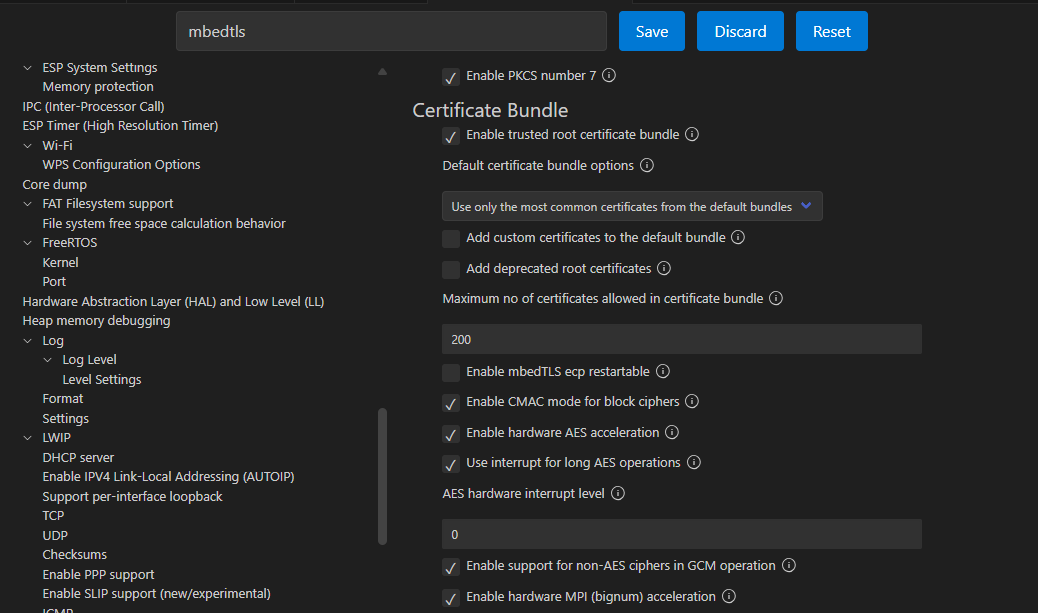
- Hit Save.
Examine the new project code
Now, let's take a look at the main.cpp file. There's more going on in this code than the previous two.
First, the code connects to a WiFi AP. This requires you to put in the valid credentials for a 2.4GHz network (the ESP32C3 does not have a 5 GHz radio). The good ones on the 5th floor lab space (hopefully where you are) are either EECS_Labs (with no password) or 608_24G with password 608g2020.
Once connected this code will send simple HTTP GET requests to a remote server that provides year-based facts in response.
Build and flash the code
Now, let's build and upload the code. Open a new ESP-IDF terminal. In the terminal, make sure you are in the \lab01b directory, and type:
...\lab01b> idf.py build
As before, the first build takes. a. while. Even longer than before because we have to build in the entire WiFi stack.
Next, to upload (flash) the code, type:
...\lab01b> idf.py flash
Finally, open the serial monitor:
...\lab01b> idf.py monitor
In the serial monitor, you should see random number facts printing out every few seconds. Your ESP32 does not internally contain all those facts, so the only way it could be printing those would be if it was getting them through the "ether"...so WiFi must be working. Nice. If you have that, that means you're good to move on!
Connecting our sensor to the internet
Specifications for this code
Now let's combine these two prior pieces of code to be able to post your sensor data to a server on the internet. You'll need to read through and understand what the code is doing in order to know how to combine. Simply concatenating the code will not work!
Here are the specs:
-
You code should set up the bh1750 sensor and take a reading every 10 seconds.
-
To do this, you'll need to add the bh1750 component to this project. If you'd like to do that via command line, the command is:
idf.py add-dependency espressif/bh1750. After adding the component you'll want to runidf.py reconfigureto update the project configuration. -
You want to then send that lux data to our server.
-
You'll want to update your
whileloop to create a POST request instead of a GET request. -
The POST request will require extra parameters for the
http_requestmethod. Hovering over the method call, you can see what those optional extra parameters are. Or you can right-click and "Go to Declaration" to inspect the code itself. The code is located under\components\6900_http_clientif the "Go to Declaration" button doesn't work.- In particular, you'll want to incorporate the data as a POST body, of the form
lux=value1&kerberos=value2. Replace your actual data forvalue1,value2 - You'll also need to provide a content type parameter, which should be
application/x-www-form-urlencoded. - The server endpoint url is
https://efpi-10.mit.edu/efi_test/lux_logger
- In particular, you'll want to incorporate the data as a POST body, of the form
Change the change the project configuration settings to include only the filter certificate bundle. You can do that via the GUI as above, but if you'd prefer to do it via the command line, in an ESP-IDF terminal, type:
>idf.py menuconfig
Then in the text-based GUI that shows up: Component config > mbedTLS > Certificate Bundle > Default certificate bundle options > Use only the most common certificates from the default bundle.
Once you've worked out what the code should be, go ahead and build.
Adjusting the partition size
Probably what will happen is that you'll get a build error of this sort:
Error: app partition is too small for binary lab01b.bin size 0x150590:
  - Part 'factory' 0/0 @ 0x10000 size 0x100000 (overflow 0x50590)
What's happening is that your code size is 0x150590 bytes, which is around ~1.4 MB. But the default block of flash allocated to storing code (the partition) is 0x10000 bytes, or 1 MB. So the code doesn't fit.
What we need to do is to increase the partition size. The ESP32C3 module that we are using has 4 MB of flash, so we can support a larger firmware. But we need to set that up explicitly.
If you are using the command line, open the menuconfig:
>idf.py menuconfig
Then select Partition table > Partition Table (Single factory app, no OTA) > Single factory app (large), no OTA.
Quit and save the configuration. This gives us space for a 1.5 MB binary.
Now when you try to build it should work.
Finally, flash and then see what happens in the serial monitor. Eventually, your code should repeatedly start printing this:
Sending POST request: https://efpi-10.mit.edu/efi_test/lux_logger
I (20113) HTTP_CLIENT: HTTP_EVENT_ON_FINISH
I (20113) HTTP_CLIENT: HTTP Status = 200, content_length = 8
Response body:
"posted"
Sending POST request: https://efpi-10.mit.edu/efi_test/lux_logger
I (25333) HTTP_CLIENT: HTTP_EVENT_ON_FINISH
I (25333) HTTP_CLIENT: HTTP Status = 200, content_length = 8
Response body:
"posted"
Once you are getting a "posted" return message, you can check to see your data on the server. Point your browser to:
http://efpi-10.mit.edu/efi_test/lux_reporter?kerberos=None
And all your data should list out.
Show your system posting to the server to a staff member.
Look ma no wires
It may not be apparent, but you are one step away from being fully wireless. Just unplug your USB cable. Yes, that's it.
So unplug your board from your laptop and then check the website. If this is all working, you should still be posting data. Congrats, you have a battery-powered IoT light monitor!
But there's an issue. That battery is discharging as we use it. And when you plug your board into your laptop, the USB data signals are transmitting back-and-forth, but no energy is being delivered to recharge the battery. So your battery will discharge and then...turn off. What we need is a way to re-charge the battery when we plug it into the laptop. We'll design and incorporate that part in EX01.
Sensing battery voltage
Measuring the battery voltage
At this point we should have a battery powered portable light sensor. One key element of battery-powered systems is knowing how much charge is left in the battery. This is known as the battery state of charge (SOC), and ranges between 0% and 100%. It's super annoying if the only way to know the battery SOC is when the system just dies (which just tells you the SOC is 0%, great).
So let's add battery sensing capabilities to our system.
Measuring the charge left in a LiPo battery is actually not trivial. In fact, it's so difficult to do that companies make dedicated ICs (called fuel gauges) to do so.
But we can get a rough sense by just measuring the battery voltage. The battery's voltage can range between 4.2 volts (100% SOC) and 3.4 volts (~0% SOC).
Where can we get access to the battery voltage directly? Not the 3.3V pin on the ESP32C3, as that is a regulated output. But you'll notice there's a VBAT pin on our mainboard, and, as you might remember, it is directly connected to the battery. So we just need to measure that voltage!
But wait. One of the challenges with doing this directly is that the ESP32's adc can only measure voltages between 0V and 2.5V. But the battery voltage is going between 3.4 V and 4.2 V. We need to somehow scale that voltage down to a max of 2.5V (otherwise our ESP would just read 2.5V).
We can use a pair of resistors to make a voltage divider. We can then safely measure the scaled down voltage in our code apply the inverse of our divider ratio, and arrive at the true pre-divider voltage measurement.
So lets just grab any two resistors off the floor, hook up our battery, and fix it in software. Not so fast.
-
We can't just use any two resistors. These two resistors will be chronically attached to our battery. If their resistance is too low, they will quickly discharge our battery, shorten our run-time, and may even turn into an LER. We should design our divider to draw less than 1 mW of power (which is still kind of a lot, but ok for now).
-
The ESP's adc will draw a (very) small amount of current from the output of the resistor divider. Make sure that the equivalent Thévenin resistance of the divider presents a negligible (<10mV) drop when the ESP's adc draws it's sampling current (1uA).
One last hardware thing. We should add a capacitor to the output of the voltage divider to smooth out the voltage measurement. This value is not as critical as the resistors from above. Anything between 1nF and 10uF should work.
Analog to digital conversion code on the ESP32C3
Now that we have conditioned the voltage signal, connect the output of the divider to an available analog GPIO of our ESP32.
To measure those voltages with the ADC, we wrote some helper code that you can use to extract the raw ADC value from the ESP and convert it to a voltage.
/* NOTE: place the following lines near the top of your main.cpp*/
#include "rom/ets_sys.h"
#include "esp_adc/adc_oneshot.h"
#include "esp_adc/adc_cali.h"
#include "esp_adc/adc_cali_scheme.h"

/* NOTE: place the following declarations and prototypes before your app_main() */
// ADC parameters and function prototypes
adc_channel_t adc_channel = ADC_CHANNEL_2;    // GPIO2, can be changed
const int num_average = 10;
static bool adc_calibration_init(adc_unit_t unit, adc_channel_t channel, adc_atten_t atten, adc_cali_handle_t *out_handle);
static void adc_calibration_deinit(adc_cali_handle_t handle);

/*NOTE: place these declarations in your app_main() */
adc_oneshot_unit_handle_t adc1_handle;
adc_oneshot_unit_init_cfg_t init_config1 = {
	.unit_id = ADC_UNIT_1,
};
ESP_ERROR_CHECK(adc_oneshot_new_unit(&init_config1, &adc1_handle));

//-------------ADC1 Config---------------//
adc_oneshot_chan_cfg_t config = {
            .atten = ADC_ATTEN_DB_12,
            .bitwidth = ADC_BITWIDTH_DEFAULT,
        };
adc_oneshot_config_channel(adc1_handle, adc_channel, &config);

adc_cali_handle_t adc1_cali_chan0_handle = NULL;
adc_calibration_init(ADC_UNIT_1, adc_channel, ADC_ATTEN_DB_12, &adc1_cali_chan0_handle);

/* NOTE: the following code will take num_average readings from the ADC and average them to reduce noise, then turn the raw values into voltage */
// Read Battery voltage
int adc_raw = 0;
int voltage = 0;
uint32_t adc_reads = 0;
for (int i=0; i < num_average; i++) {
    ESP_ERROR_CHECK(adc_oneshot_read(adc1_handle, adc_channel, &adc_raw));
    ets_delay_us(10);       // blocking delay in us
    adc_reads += adc_raw;
}
adc_reads = adc_reads / num_average;

printf("ADC Raw Data: %d\n", (int)adc_reads);
//maybe handle any errors later:
ESP_ERROR_CHECK(adc_cali_raw_to_voltage(adc1_cali_chan0_handle, adc_reads, &voltage));


/* Note: place these functions at the end of your main.cpp, after the app_main() block */

/*---------------------------------------------------------------
        ADC Calibration (put outside the extern C block)
---------------------------------------------------------------*/
static bool adc_calibration_init(adc_unit_t unit, adc_channel_t channel, adc_atten_t atten, adc_cali_handle_t *out_handle)
{
    adc_cali_handle_t handle = NULL;
    esp_err_t ret = ESP_FAIL;
    bool calibrated = false;


    if (!calibrated) {
        ESP_LOGI(TAG, "calibration scheme version is %s", "Curve Fitting");
        adc_cali_curve_fitting_config_t cali_config = {
            .unit_id = unit,
            .chan = channel,
            .atten = atten,
            .bitwidth = ADC_BITWIDTH_DEFAULT,
        };
        ret = adc_cali_create_scheme_curve_fitting(&cali_config, &handle);
        if (ret == ESP_OK) {
            calibrated = true;
        }
    }

    *out_handle = handle;
    if (ret == ESP_OK) {
        ESP_LOGI(TAG, "Calibration Success");
    } else if (ret == ESP_ERR_NOT_SUPPORTED || !calibrated) {
        ESP_LOGW(TAG, "eFuse not burnt, skip software calibration");
    } else {
        ESP_LOGE(TAG, "Invalid arg or no memory");
    }

    return calibrated;
}

static void adc_calibration_deinit(adc_cali_handle_t handle)
{
    ESP_LOGI(TAG, "deregister %s calibration scheme", "Curve Fitting");
    ESP_ERROR_CHECK(adc_cali_delete_scheme_curve_fitting(handle));
}
One more thing is that you will have to add 'esp_adc' to the REQUIRES list of your CMakeLists.txt in the \main directory.
You can change the GPIO you use for the ADC, just make sure to use one of the GPIOs that are connected to ADC1, basically GPIO0 thru GPIO4, though we recommend using GPIO2..4.
This piece of code returns the voltage present on the specified analog GPIO pin. Make sure to "undivide" the voltage divider ratio to get the actual battery voltage.
Incorporate this functionality into your code, and make sure your system is correctly measuring voltage (get a multimeter and actually confirm). It should be reasonably close (within 5%). Depending on your battery's charge, your system should measure a voltage between 3.4 and 4.2 volts.
Going from voltage to SOC is not trivial, so for now, we're just going to report the battery voltage.
Tying it all together
Let's finish this lab.
Your final system should still make POST requests every 10 seconds with your kerberos (kerberos), lux (lux) and battery voltage (bat).
Once you see your data being posted to the server and can view it on the webpage, you'r finished! In EX01 we'll change from the efpi-10 endpoint to your own server, and use those logs to verify that your system is working.
Show your battery-powered system posting your data including battery voltage to the server to a staff member.