Lab 4
Please Log In for full access to the web site.
Note that this link will take you to an external site (https://shimmer.mit.edu) to authenticate, and then you will be redirected back to this page.
Overview
Today you're going to get some experience with the Joulescope in a number of situations. Power should be at the front of everyone's mind on this project even if you're not "doing the power part." So everyone in the team should be fluent in these concepts. The lab uses the Joulescopes, of which we currently have five, and those are to stay in lab. Anybody caught removing a Joulescope from lab will be punished.
We have a limited number of Joulescopes, so please sign up for a time here when you can use one.
We'll study power using the Joulescope in the following situations:
- A LED being driven by 5V USB with an in-series variable resistor.
- The power consumed by our ESP32-C3 with some basic LED flashing code.
- The power consumed by our ESP32-C3 in different modes of operation (WiFi on, WiFi transmitting, light sleep, deep sleep)
- The power curve of a photovoltaic cell.
Joulescope Setup
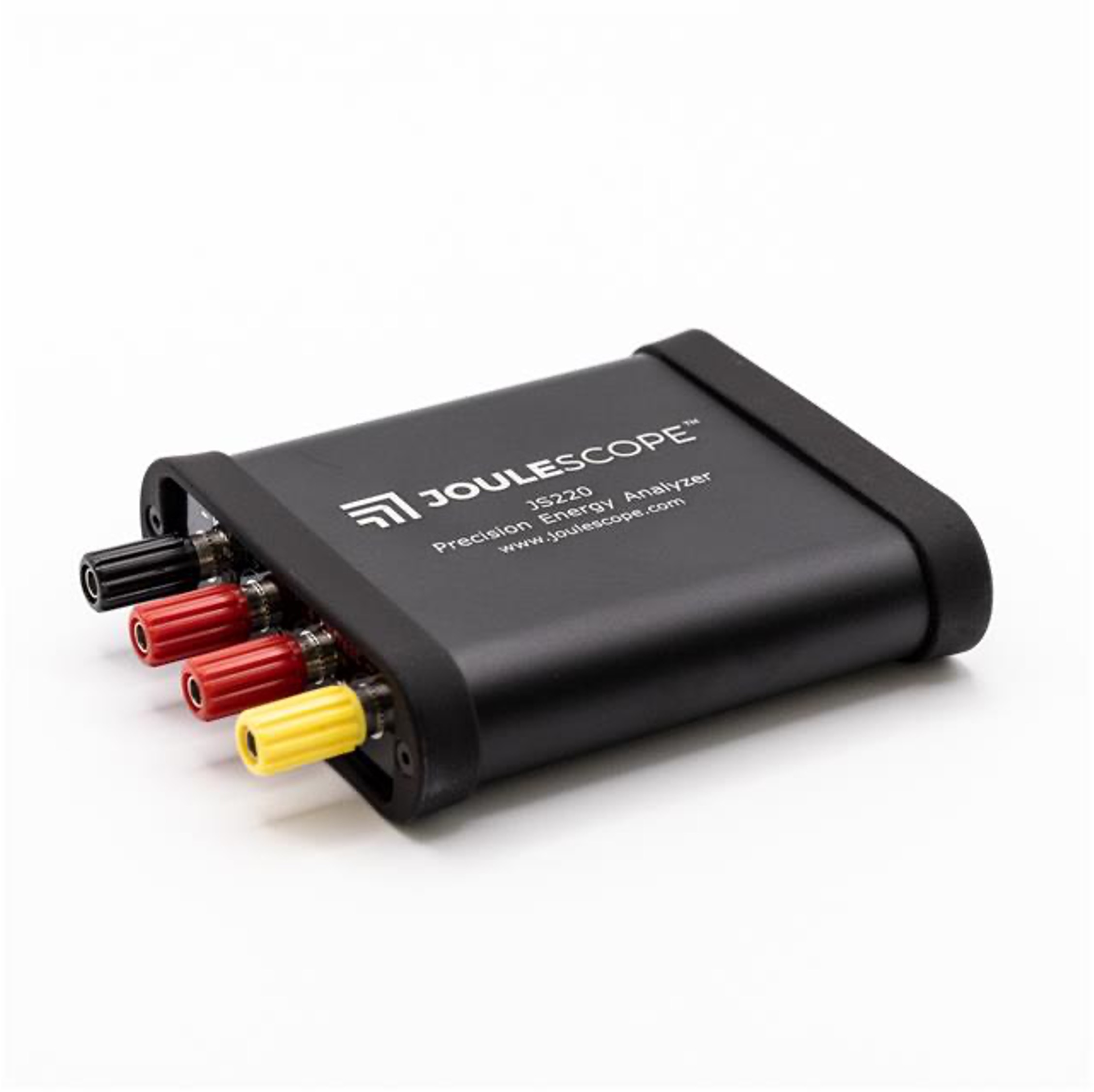
Here's the Joulescope. They are very nice system tools. Treat them with respect.
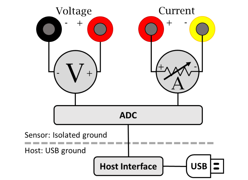
As we discussed in lecture, the Joulescope is a very nice system which, when hooked up correctly will at a very rapid rate utilize an internal ADC to make measurements of the voltage across a region of a circuit and the current into that system. Of course, we have to hook it up correctly for it to do this (discussed below). It might seem like what this is doing is not that hard, but the devil is in the details. It is pretty easy to make a power measurement system that works ok-ish for a limited range of power. It is much, much harder to make one that can dynamically adjust itself for a wide-range of powers as the Joulescope does; it has some fantastic engineering in it.
First task at hand is to get the software to work with our Joulescope. Now maybe I just have really low standards from a lifetime of using hardware design and measurement tools, but I'm blown away by how well this Joulescope software works. Go to their website here. Download the software for the JS220 for your appropriate system. It should just work, but let us know if you have any issues installing. I'm sure Windows will somehow make it a challenge. (Note from Joel: No, Windows is a modern operating system and will work just fine. Now, MacOS, who knows...)
Once you've got it, open it up and then plug in your Joulescope. For lab today we'll largely be concerned with using two "widgets": (1) the multimeter and (2) the waveform (turn them on from the Widgets pull-in in the top menu.)
These all kinda show the same data, but they give it to us in different formats to make it easier to consume. If you just want rough ideas of power being consumed (or current or whatever), you can look at the "multimeter". If you want to see and measure tiny "blips" of power consumption like from a transfer of data over WiFi, the waveform viewer (which can be saved btw) would be the choice.
The widgets should just start working when you plug in the Joulescope. Again let us know if there's any issues. The readings won't make much sense until you're actually hooked up.
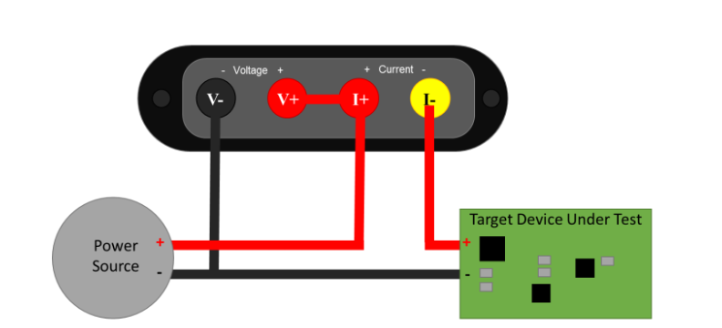
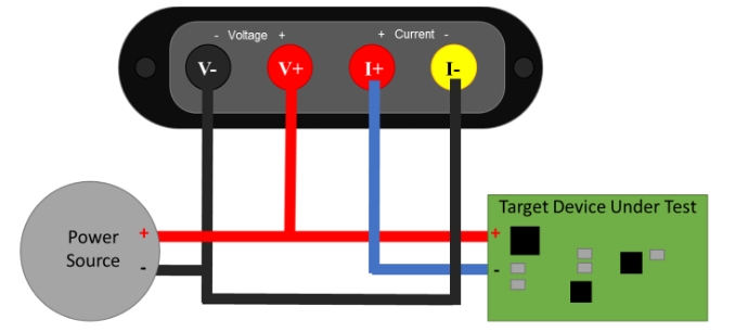
As mentioned in class, there's two ways to measure power consumption (and specifically the current portion), a high-side measurement or a low-side measurement. The two options are shown below, but for today we'd recommend you measure using a high-side configuration.
A Simple First Circuit
For a first circuit, just to get our feet wet, let's build the following:
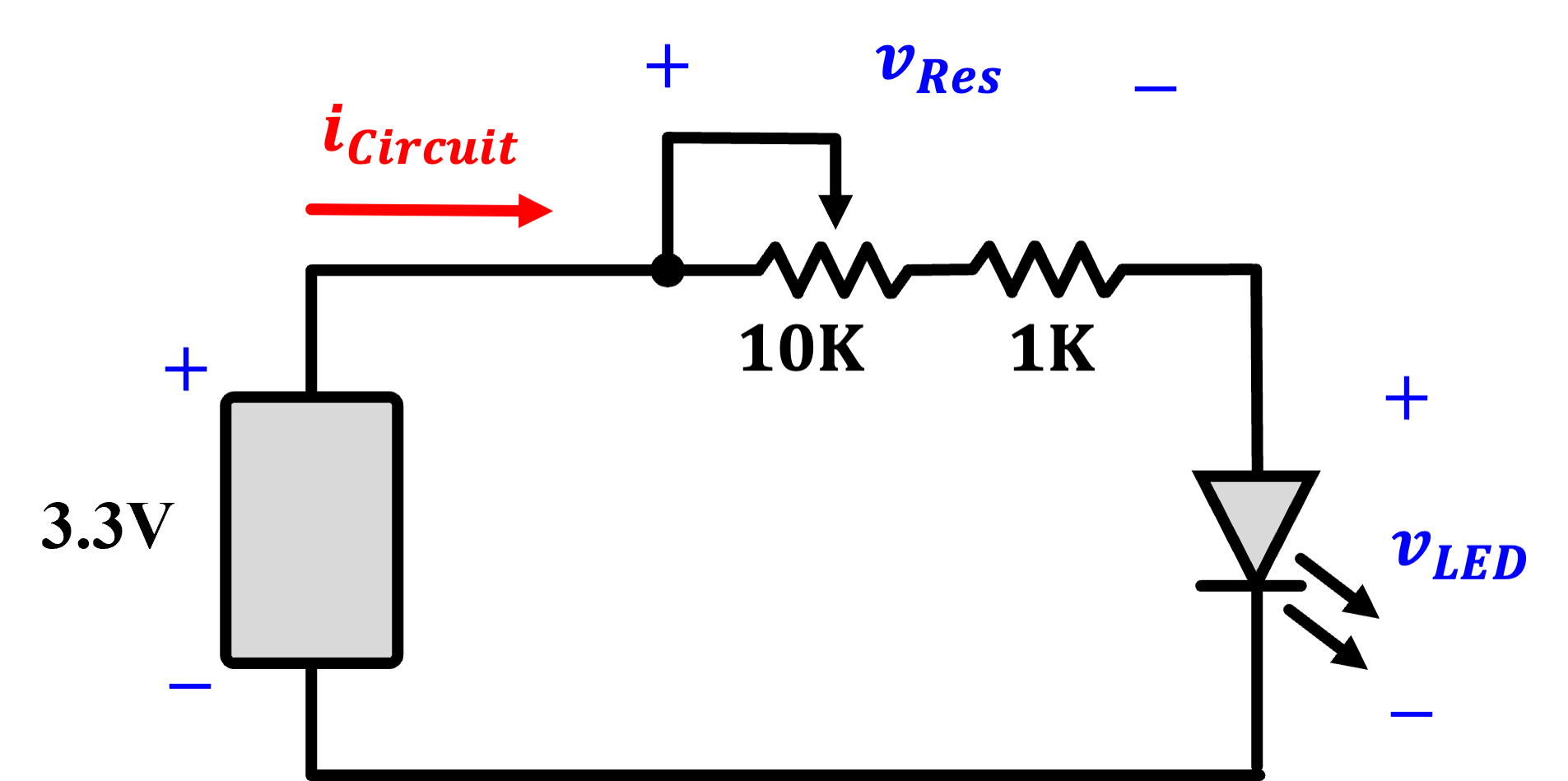
The 3V3 source you can get from your board super easy. Use a fixed 1K resistor and a variable 10K resistor to regulate the flow of current into a red-colored LED. What the circuit will do, at a high level, is vary the brightness of the LED. Build it, power it from your computer or whatever, and just verify it works. When that is done, make a high-side measurement of the circuit's power consumption (resistors and all) by integrating the Joulescope into it.
First:
- Measure the voltage across the entire resistor-LED system and the current through it. In this placement, the voltage should largely be constant since it is what the regulator is providing. You should see the current, and therefore power, vary significantly as you sweep the potentiometer.
Then:
- Measure the voltage across the LED specifically while still measuring the current through the whole system. This should now tell you what power the LED on its own is consuming. It should, hopefully if there is a rational god, be less than the number you're getting when you measure what the entire circuit is consuming. Ok noice. Onto the next circuit.
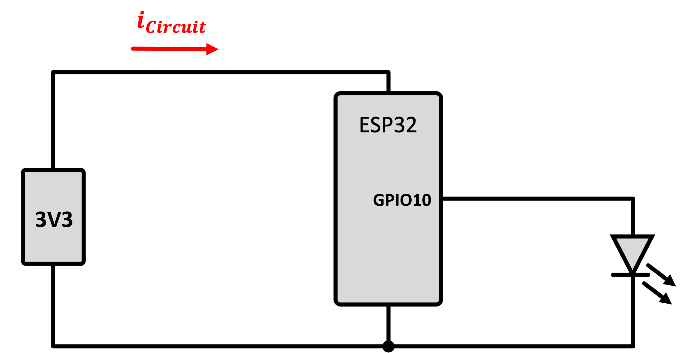
The ESP32-C3
The ESP32-C3 is capable of some pretty interesting behavior related to its power consumption. Unfortunately, especially for the low-power modes, if your system has other components consuming power then those will dominate the power measurements. For example, on our mainboard and some of the peripheral boards there are:
- The always-on GREEN power supply indicator LEDs on the mainboard and the BMS board (each consuming about ~2-3 mA at @3.3V)
- The LDO regulator that converts the battery voltage to 3.3V
Luckily, we've built our mainboard with two jumpers, and now we can see why. JP11, which is labeled "TO REG", is upstream of the LDO and the green mainboard LED. JP2, which is labeled "TO SYS" is downstream of the LDO and green LED, and only upstream of the ESP32-C3 (and anything connected to it).
So if we want to measure the power into the mainboard, we'd open the circuit at JP11 and insert the Joulescope current measurement. If we want to measure the power into the ESP32C3 itself (and anything it is driving), we'll use JP2. For today, let's use JP2.
Get a blue or white LED and hook it up to GPIO 10 on the ESP32 like shown below. We're going to flash some LED since the serial port will be problematic in our testing.
Make a new ESP-IDF project.
For code, let's use this short, sweet simple program that flashes the LED. Here it's shown entirely in C, so no extern statemenet needed, though feel free to use C++ if you prefer. Program it to make sure it is even working.
#include <stdio.h>
#include "freertos/FreeRTOS.h"
#include "freertos/task.h"
#include "driver/gpio.h"


gpio_num_t BLINK_GPIO = GPIO_NUM_10;

void app_main(void)
{
    // Configure the GPIO pin
    gpio_reset_pin(BLINK_GPIO);
    gpio_set_direction(BLINK_GPIO, GPIO_MODE_OUTPUT);

    int state = 0;

    while (1) {
        state = !state;
        if (state) {
            printf("LED ON\n");
        } else {
            printf("LED OFF\n");
        }
        gpio_set_level(BLINK_GPIO, state);
        vTaskDelay(1000 / portTICK_PERIOD_MS); // Delay 1 second
    }
}
Now once you're sure the flashing is good, integrate the Joulescope in so that you're measuring the power consumed by the ESP32-C3. Watch the plot of the voltage, current, and power. You should see very distinctively different regions of power consumption. What do the high and low regions correspond to?
Once that makes sense, go in and change your code so that the LED is flashing 100 times a second instead of once a second (also comment out the two print statements so you don't clog your serial monitor). Once this is done, your eye will barely be able to keep up and instead see a seemingly steady light, or perhaps, if looked at indirectly, just the slighest soupçon of a flicker using the rods of your peripheral vision. But the Joulescope should be able to keep up. It should be able to give you a plot of the instantaneous power being used by your ESP32 because of it either driving or not driving the LED. Very cool.
The ESP32 Doing Other Things
Flashing an LED is fine but a little artificial. What we wanted the last part to demonstrate is that software can cause differences in the power being used by the ESP32. Let's see this taken to the extreme.
The code below does a few things. It is a variant of the same code you used in Lab 1 but with some modifications. Roughly speaking it:
- Upon powering up it flashes an LED five times.
- It runs on a cycle.
- On the first cycle of every ten, it connects to the WiFi and gets a fact from Wikipedia.
- For most cycles it sends the ESP32C3 into light sleep for 3 seconds. After waking, the LED flashes twice.
- Every tenth cycle, it instead sends the ESP32 C3 into a deep sleep for 10 seconds. Coming back from sleep puts the code back at the beginning, resulting in the LED flashing five times.
This code is a very simple (and perhaps uselessly short) example of putting the ESP32C3 through its paces for different power modes and how you may be able to utilize it for the project.
Create a new ESP-IDF project. Edit the main CMakeLists.txt to the following:
idf_component_register(SRCS "main.cpp"
                    INCLUDE_DIRS "."
                    REQUIRES 6900_wifi 6900_http_client
                    PRIV_REQUIRES esp_driver_gpio)
We want to include both the 6.900 WiFi and HTTP libraries, and because the ESP32-C3 build system gets fussy sometimes, we need to also explicitly include esp_driver_gpio.
Add a components directory to your project, and place copies of the 6900_wifi and 6900_http_client libraries in there.
Rename the .c file to main.cpp, and add in the code below.
Run the code and study the power consumption in the different modes. Pay particular attention to the different sleep modes and the activity during the WiFi transactions. Make notes of the different numbers (lowest power, highest power, etc). Try to tie them up with their different modes! Get a plot of the ESP32 performing WiFi requests and going into different sleep modes.
See how your computer behaves with the ESP32 C3's USB port. Because the USB PHY on the ESP is getting either clock-gated or power-gated your computer may respond to it weird and/or ignore it. This is why using a indicator like an LED is a nice tool here since it can tell you roughly what area/state of behavior it is in.
#include <stdio.h>
#include <string>
#include "freertos/FreeRTOS.h" // ESP32 RTOS
#include "freertos/task.h"
#include "freertos/event_groups.h"
#include "esp_random.h"
#include "6900_wifi.h"
#include "6900_http_client.h"
#include "driver/gpio.h"
#include "esp_sleep.h"

void get_wifi();

// SSID and credentials
const char *ssid = "EECS_Labs";
const char *pass = "";

static WiFi wifi;       // static (single, long-lived) WiFi instance
static http_client hc({.keep_alive = false});


gpio_num_t BLINK_GPIO = GPIO_NUM_10;

extern "C" {
void app_main(void) {

    printf("Starting up!\n");

    gpio_reset_pin(BLINK_GPIO);
    gpio_set_direction(BLINK_GPIO, GPIO_MODE_OUTPUT);

    int state = 0;

    //five flashes on waking up from deep sleep or setup
    for (int i=0; i<5; i++){
        gpio_set_level(BLINK_GPIO, 1);
        vTaskDelay(100 / portTICK_PERIOD_MS);
        gpio_set_level(BLINK_GPIO, 0);
        vTaskDelay(100 / portTICK_PERIOD_MS);
    }


    while (1) {
        printf("I'm up!\n");
        if (state==0) { //once in ten cycles get a number fact over WiFi
            get_wifi();
        }
        state += 1;
        state %= 10;

        printf("%d\n", state);
        printf("Going to sleep\n");
        if (state==9) {
            esp_sleep_enable_timer_wakeup(10000000); // how long to sleep in us
            esp_deep_sleep_start();
            //deep sleep will effectively restart the system (everything turns off)
        }else{
            esp_sleep_enable_timer_wakeup(3000000); // how long to sleep in us
            esp_light_sleep_start();
            //light sleep *should* just come back here when finished, but note
            //two flashes on waking up from deep sleep or setup
            for (int i=0; i<2; i++){
                gpio_set_level(BLINK_GPIO, 1);
                vTaskDelay(100 / portTICK_PERIOD_MS);
                gpio_set_level(BLINK_GPIO, 0);
                vTaskDelay(100 / portTICK_PERIOD_MS);
            }
            printf("Back from sleeping!\n");
        }
    }
}
}

void get_wifi() {
    uint8_t count = 0;
    printf("Connecting to WiFi");
    wifi.begin(ssid,pass);
    while (wifi.status() != WIFI_STA_CONNECTED && count < 10) { //can change this to more attempts
        vTaskDelay(pdMS_TO_TICKS(1000));
        printf(".");
        count++;
    }
    if (wifi.isConnected()){
        printf("Connected!\n");
    }

    std::string request_buffer = "https://en.wikipedia.org/api/rest_v1/page/summary/";
    request_buffer += std::to_string(esp_random() % 2025);

    std::string temp = "Sending GET request: " + request_buffer + "\n";
    printf(temp.c_str());

    hc.http_request(request_buffer.c_str(),HTTP_METHOD_GET);
    printf("Response body:\n");
    if (hc.body_is_text()) printf(hc.body_cstr());
    printf("\n");
    wifi.stop();    // good practice to stop wifi radio before going to deep sleep
}
Show your working Number-getting-power-saving system.

In general, with the ESP32 when it goes to light sleep and comes back, it will pick up right where it left off (you can almost think of esp_light_sleep_start() used in conjunction with a timed wakeup as a low-power delay call.) Potential issues with the USB aside, it should just start again. The deep sleep functionality nukes the SRAM, however so the entire state of the system is gone. As a result if you do a timed deep sleep, when the system wakes back up it essentially is almost like you just pushed the reset button. The system starts anew at the beginning. This sucks since state and things are all gone.
The ESP32 C3 does have a special small portion of memory (8 KB vs the ~400 KB) that will stay powered during deep sleep. This memory, known as the RTC Memory can be used just as any other memory. The easiest way to get access to it is to use a select set of prefixes when declaring variables. Let's say we wanted a variable to live in the RTC memory. All you need to do is declare and define it like so in the global scope:
RTC_DATA_ATTR int my_variable = 7;
On first power up the variable will start at value 7. You can then do whatever you want to it in your code. If you set my_variable to 11 and then have the ESP32 C3 take some Nyquil (aka esp_deep_sleep_start()) when it wakes up my_variable will still have 11 in my_variable. You can create whatever type of variables you want in this memory (within size limitations which are...again...8KB).
There are other prefixes you can use like the following if you don't care to set a value with your variable initially:
RTC_NOINIT_ATTR int my_variable;
OK, we'll come back to this in a little bit.
Solar Cell Analysis
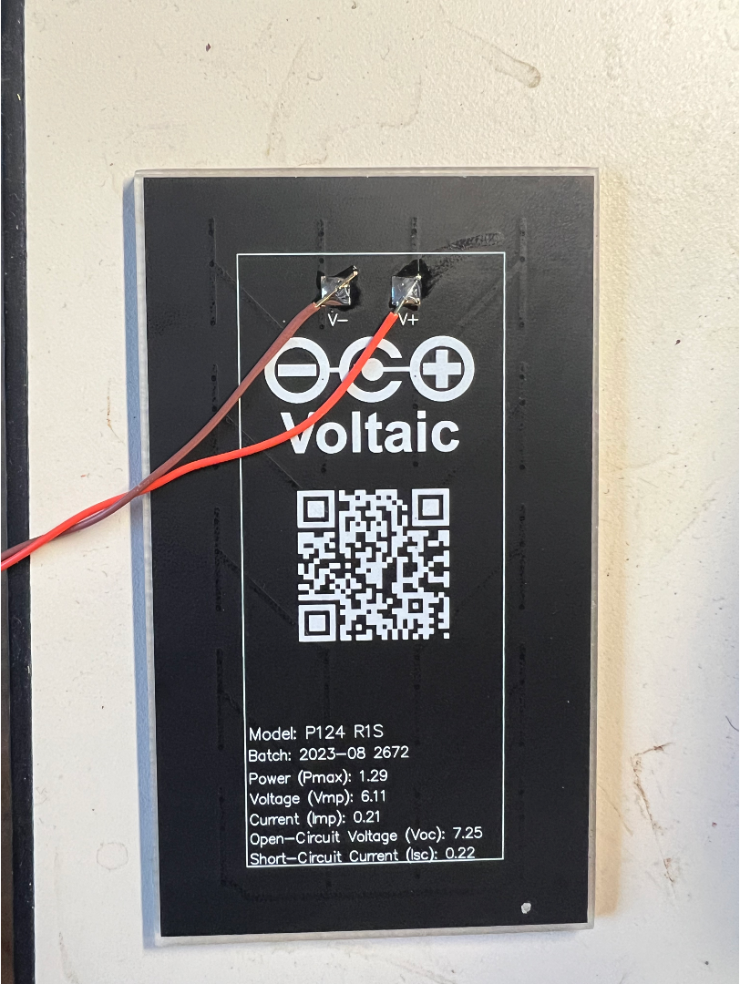
Before we move onto the final task at the end, which involves some coding, we're going to do one more thing with the Joulescope. Grab one of the photovoltaic cells we have already pre-soldered wires onto. Notice the specs on the back of this particular cell say that its Pmax is 1.29W. That is a very hopeful number. This panel will likely deliver 1.29W when under very bright, direct sunlight and when you are using the element at its maximum power point that we talked about in class. In lab today we're going to use the cell under room lighting and you will be super surprised at just how awful that is. If you get a few mW out of it, that'll probably be something to celebrate.
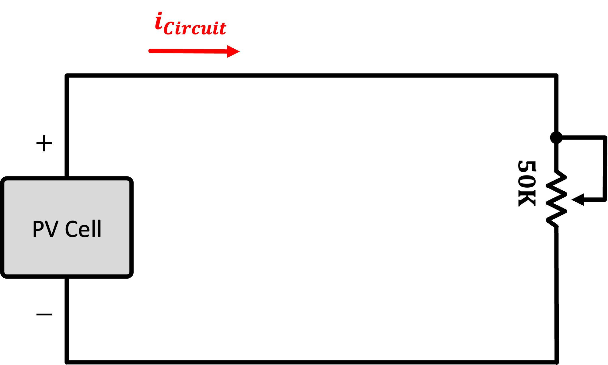
A Variable Load
So as a first circuit, grab a potentiometer (I think a 50K is usable), and measure the power consumed by it (or alternatively the power supplied by the PV cell, same difference). While monitoring the power, vary the potentiometer from one extreme to another. At both extremes you should see minima of power (it might not quite be 0, but it'll be down there). Somewhere in the middle of the potentiometer range, you should be able to find a point where maximum power is being delivered to the resistor. This is the maximum power point.
Make note of this MPP and also try to see how it varies as you put more light on it (perhaps your cellphone, or if the new Schwarzmann College of Computing is reflecting the blinding rays sunshine into the room) maybe you can actually get some actual power out of it.
A Fixed Load
In the previous circuit you actually adjusted the load to satisfy the PV cell's characteristics. Not all devices in life can be varied like the potentiometer. Consider another diode...this time an LED, a cousin of the PV cell, just used differently and designed to give off light from electrical energy rather than make electrical energy from light. This LED has its own I-V curve that is non-variable. When you assemble a circuit of the PV cell driving this LED you will now have essentially two somewhat stuborn devices trying to exchange energy, and their ability to do so with a high efficiency (such as at the MPP of the cell) may just not be possible.
Build the circuit below. Don't worry about a current-limiting resistor. Unless you are outside or getting beams of light reflected from the Schwarzman building, there's no way the cell will be generating enough to burn the LED out. Try to see what power you can harvest from the cell. Can you get the LED to light? How do you feel about this system?
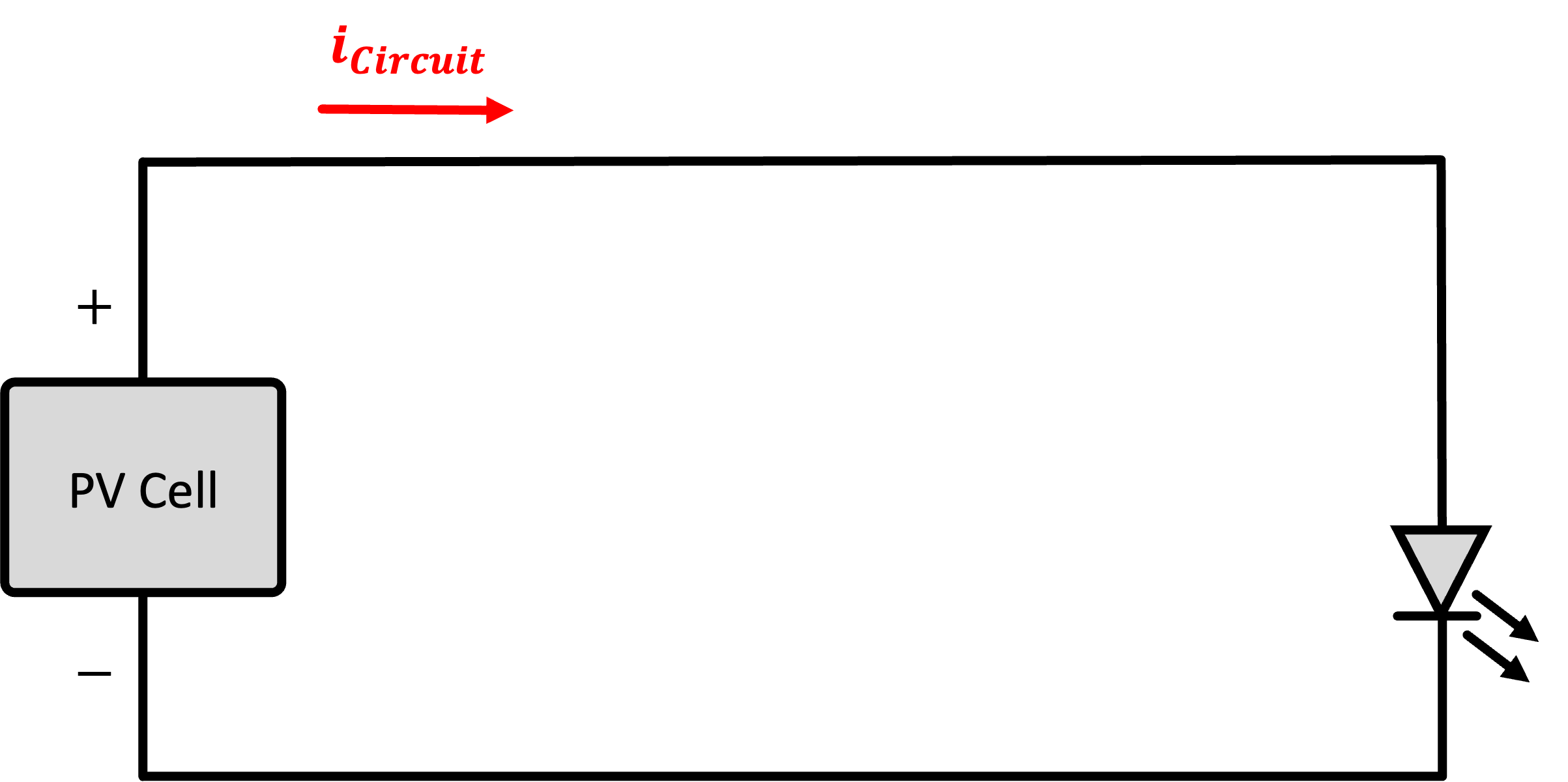
Show your working photovoltaic system powering an LED to a staff member. Make sure Joulescope is hooked up to give you power measurements.
Mini Final Assignment
OK, you should be done with the Joulescope now, so feel free to release it to another student.
Your assignment, if you choose to accept it (which you don't really have a choice since it is required) is to write a program that does the following:
- Starts up and runs.
- First time through the loop it flashes its LED one time (on-then-off at 100 ms each).
- Then it goes to deep sleep for five seconds on a timer.
- Then the device wakes up, flashes its LED two times (also at the 100ms rate)...then back to deep sleep for five seconds.
- Then the device wakes up, flashes its LED three times (also at the 100ms rate)...then back to deep sleep for five seconds.
- Then the device wakes up, flashes its LED four times (also at the 100ms rate)...then back to deep sleep for five seconds.
- etc...
- etc...
- All the way to:
- Then the device wakes up, flashes its LED twelve times (also at the 100ms rate)...then back to deep sleep for five seconds.
- Before resetting back to 1 flash
You will need to use a RTC variable for this since sleep-wake cycle to sleep-wake cycle, information needs to be retained. Remember every time it comes back from deep sleep it will start in setup again.
Feel free to remove (or not) all the WiFi stuff from your code so it compiles faster. Get the code working and when done, submit just your main.cpp file below: