BQ25185 BMS design
Please Log In for full access to the web site.
Note that this link will take you to an external site (https://shimmer.mit.edu) to authenticate, and then you will be redirected back to this page.
Learning Objectives
In this exercise, you'll choose a few resistors for the BQ25185 battery management system, enabling you to charge your battery!
Battery management
In Lab01 we set up a battery-power cloud-connected system. Pretty cool. But you may have realized that your battery is discharging while it's being used, and as of now we have no way to re-charge it.
So we need some sort of integrated circuit to charge the battery. LiPo batteries can be dangerous, so specialized ICs are used to make sure the batteries charge at the right rate and to the right voltage.
But it gets even more complicated. If we're running off of the battery, and the battery gets too discharged, we'd like to be able to plug the system in, and have the system continue working, while the battery is charging. After all, when you plug your phone in to charge, you expect the phone's battery to charge and the phone to still work.
So really what we need is some magical IC (or ICs) to manage the power, directing power to/from the battery, to the system, from the wall, and so on. Sounds complicated.
Luckily, it's complicated but extremely commonly needed, and hence companies have created solutions to do this. These systems go under various interrelated name: battery management system (BMS), power management IC (PMIC), battery chargers, and so on.
That's what our bq25185 board does. The bq25185 chip on this board (~$1.20! at our quantities), includes "load sharing" (aka automatically directing power to the system or the battery), and battery charge management (charge the battery).
Basically, the system operates in a few different modes:
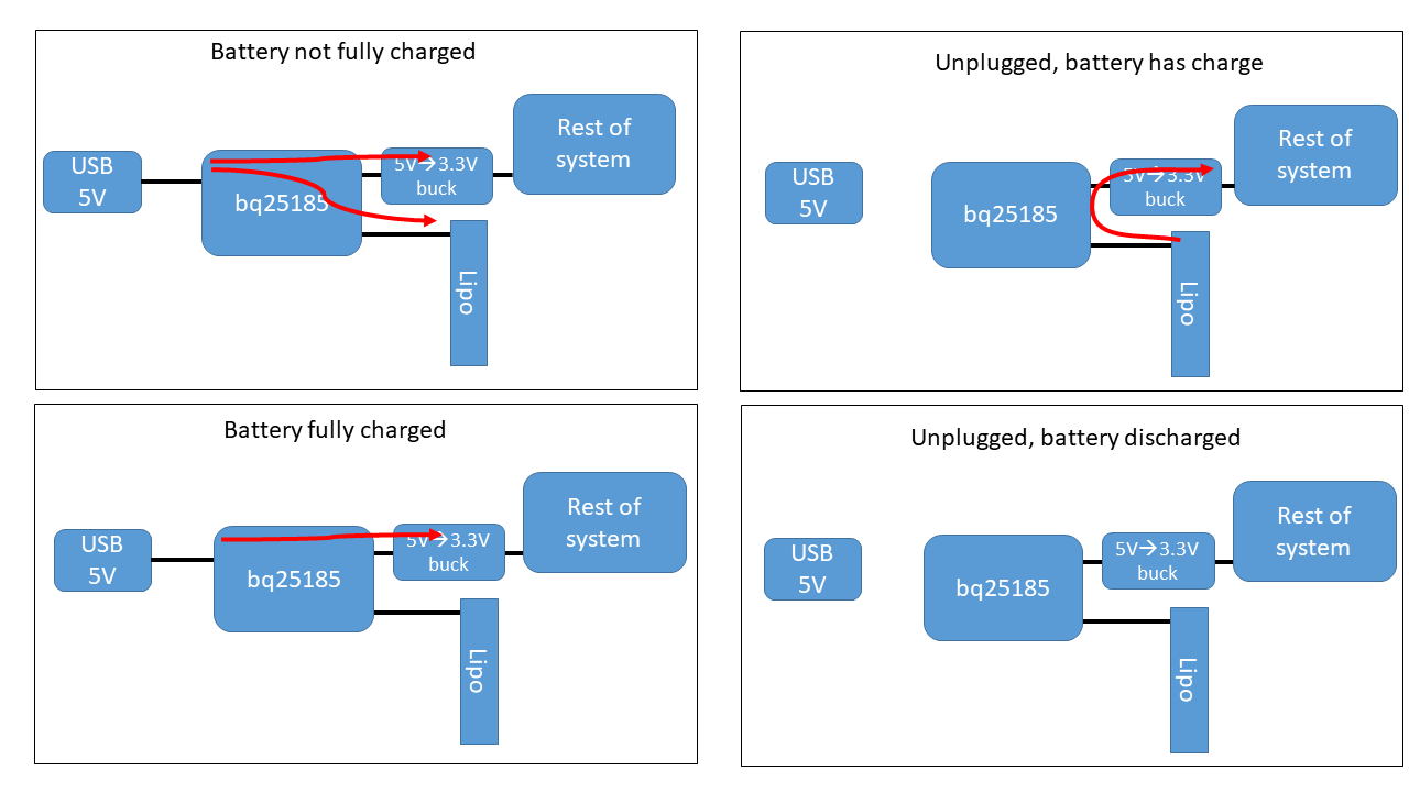
However, the bq25185 board we're giving you has some but not all components on it. You'll need to choose some values and then solder them on.
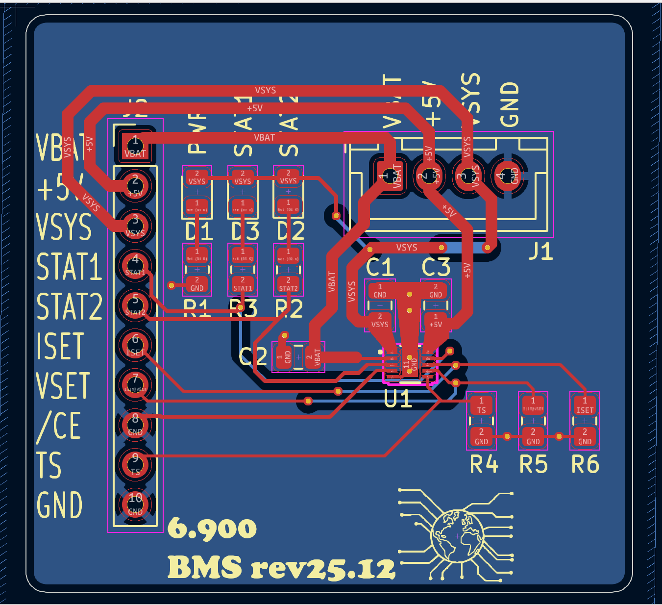
Schematic and PCB
We've provided a view of the schematic and PCB for this board below:
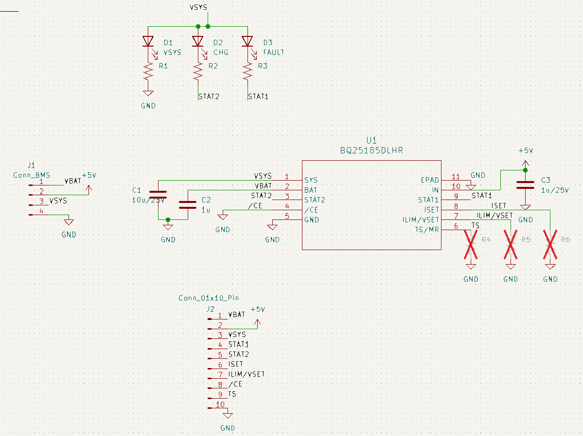
R4
R4 goes between the TS/MR pin and ground. This allows the device to be manually reset (MR) or to be connected to a thermistor to measure the battery temperature (TS). For our simple system here, we are not using it.
So what do we do with that pin if we're not using those functions? Basically, we need to scour the datasheet to find out. We'll make your life easier for this one: check out section 7.3.9.1.

R5
Next we have R5, which is connected between the ILIM/VSET pin and ground. This sets the maximal current that can go thru the bq25185.
One way that sometimes works to help choose component values is to look at the pin definitions table in Section 6. Follow that and you should soon be able to determine the proper value for R5, under the conditions that we want the maximum current limit and we want a maximum battery voltage of 4.2, which is typical for Li-Ion batteries.
R6
Finally, we have R6, which is connected between the ISET pin and ground. This sets the maximal charge current for charging the battery. We want to go fast, so let's choose the maximum current allowed, which from I_{CHG\_RANGE} in the datasheet is 1000 mA.
Now, go thru the datasheet carefully and you'll find a section that tells you how to pick R_{ISET} aka R6 based on this desired charge current.
Assemble
Find your parts
-
Find a bq25185 board from the staff table.
-
Find those resistors in 0805 packages from the little parts bin.
Apply solder paste
-
First, apply solder paste using the syringe to the pads (six in total). Even more so than for the LDO board, here the components are a bit smaller, so you'll want less paste!
-
Place the parts on the pads with tweezers. The orientation of the resistors does not matter for our board, though have them face up so you can read the numbers.
Once your parts are on the board, take it to a hot air station and let the air flow!
Using the Hot Air Station
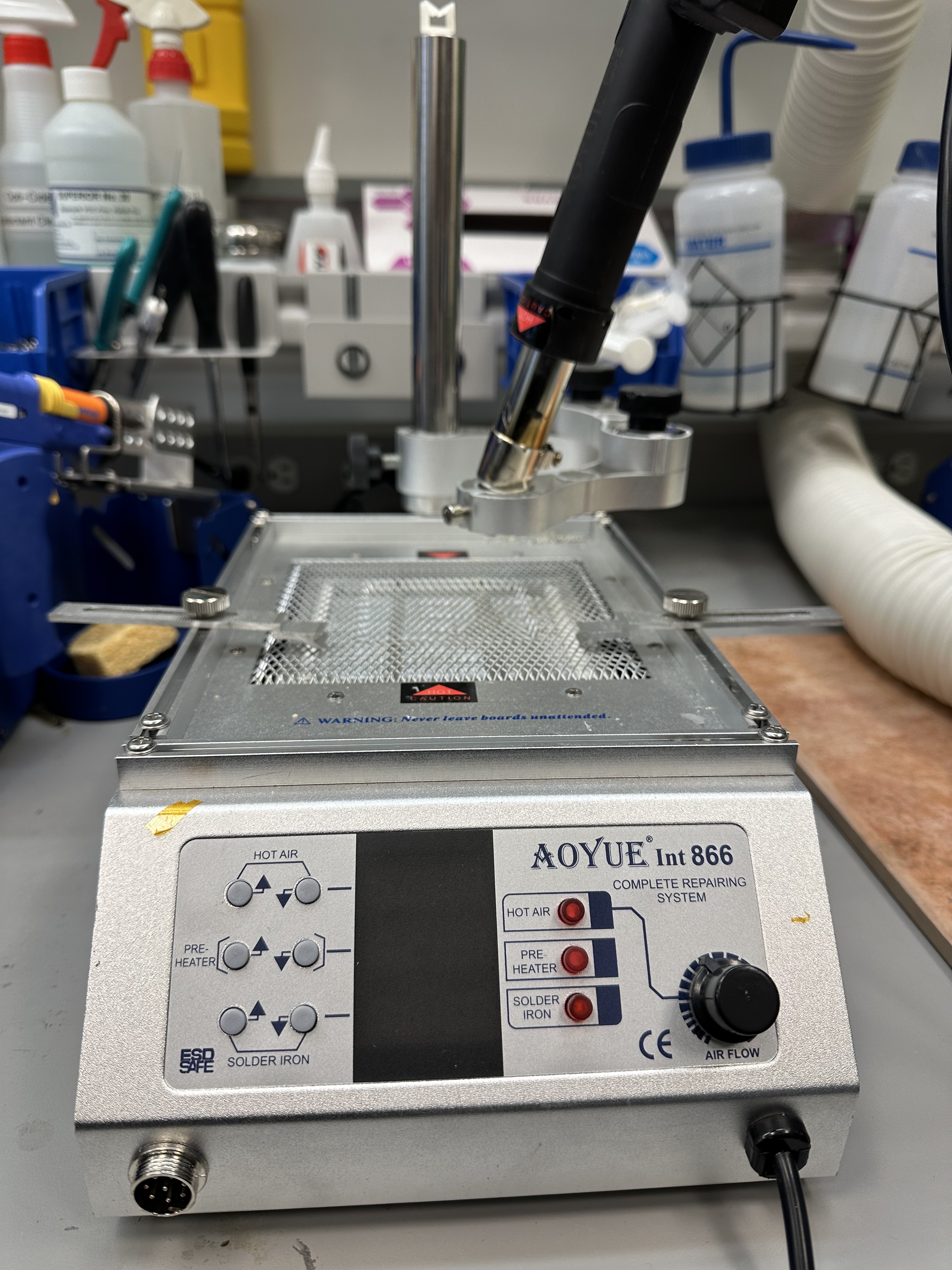
-
Turn on the station: the power switch is located at the back of the machine. All the LEDs should display OFF, indicating that the hot air, bed (pre-heater), and soldering iron are all turned off.
-
Press the red button corresponding to the bed and set the temperature to 180 C by holding on the up button.
-
Now, using tweezers, place your board between the clamps above the pre-heating bed.
-
Turn on the hot air gun and set its temperature to 325 C.
-
When the gun reaches our desired temperature, bring the hot air over your board, point it at the resistors, and wait for the solder paste to reflow. It'll go from a dark grey paste to a chalky light grey, and then to a shiny silver liquid, same as when we did hot plate reflow.
-
Once you have all 3 resistors reflowed, remove the hot air, and then use tweezers to remove the board from the station.
-
Next, turn off the hot air and the bed by toggling their corresponding red buttons. You will hear the automatic cool-down in the hot air gun start. While you wait for the built-in fan in the hot air gun to stop runnning, also wait for your board to cool and the solder to solidify. Once the fan stops, turn off the hot air station.
Move your jumper
- Next, you'll want to move your BMS/NO-BMS jumper on your mainboard from the NO BMS situation to the BMS situation.
Attach tbe bq25185 board
- You'll notice that there are two posts on the 3DP backplane that line up pretty perfectly with the holes on the bq25185 board. Use those to attach the board to the backplane using 6-mm long M3 screws, same ones we used in lab01.
Cable
To connect the bq25185 board to the mainboard, we will be using a JST-style cable. JST connectors are a type of crimp connector that is commonly used to connect boards, and we want to give you some experience with them, in case you decide to use it for your project.
You can find JST connectors with different pitches between leads. Here we are using 0.1" or 2.54mm pitch, though 2mm and finer are also available.
That said, we are going to make your life a bit easier, by allowing you to use wires that have pre-crimped pins, because crimping JST pins is kind of annoying. You can thank us later.
-
Obtain two (2) 1x4 housings and four (4) pre-crimped wires from the staff table. You can choose any color you want for the wires.
-
Next, insert the wires into the housings. Here it is critical that the wire on pin 1 of housing 1 ends up on pin 1 of housing 2. Else you won't be connecting the right signals together.
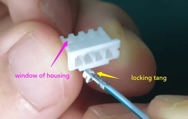
When inserting the wires, make sure that the flat part of the crimp pin (locking tang) is oriented toward the little window on the housing, like in the image below (thanks useful website with images. If you do it right, when you insert the wire you will hear a little click, and the wire will not pull out when you give it a gentle tug.
- Repeat for all four wires, again making sure that the wires go to the corresponding locations on the housings.
Connect and test
Now, use your new cable to connect the bq25185 board to the mainboard.
With your battery in its holder, you should see your green LED on the mainboard light up, and the green LED on the bq25185 board also light up.
Then, connect the USB connector to your laptop or a charger plug. You should see the orange stat2 LED light up on the bq25185 board.
Now, make sure your ESP32 is loaded with the firmware from lab01 to post the battery voltage to your server. Set up your tunnel and monitor your server's GET endpoint for at least 20 minutes. You should see your battery voltage creep up by at least 50-100 mV over that time. If your voltage is not increasing, please come to OH for help, since your system will die without a way to recharge.