Enclosure Design
Please Log In for full access to the web site.
Note that this link will take you to an external site (https://shimmer.mit.edu) to authenticate, and then you will be redirected back to this page.
In this exercise, we'll design a 3D-printed enclosure for our MILO boards, and CAD it in Fusion 360. And once you export your part geometry, the staff (Fischer) will print them in our state-of-the-art precision manufacturing facility (his basement). Fundamentally, we'll be designing something similar to this:
The steps for this are relatively straightforward, so let's jump in!
Fusion 360?
You should have access to Fusion 360 from when you ran through the software setup, either because you installed it (if you're on Windows/MacOS) or because you're using it in a browser window (everything else). If you don't, the instructions are there.
Fire up Fusion, make sure you're signed in, and you should see a new project in front of you, like this:
Start a new Project
In the Data Panel at the left of the Fusion 360 window, select New Project. Give it a good name. ow go ahead and Save. Give your design a fantastic name.
Then double-click on that project and you should see a gray window with an Upload button. Good. N
Import CAD from Altium 365
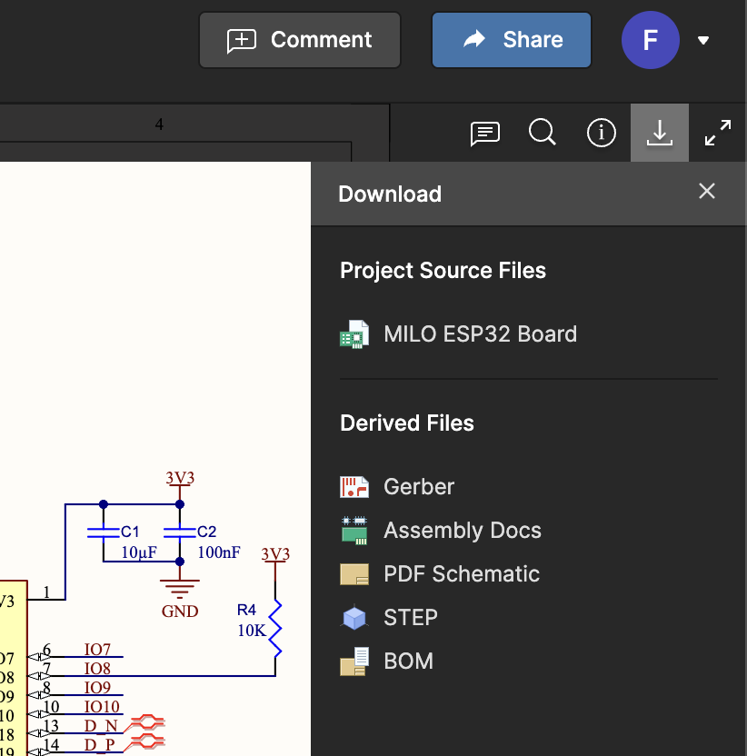
Our enclosures will need to hold the boards we've just put together, so we'll want to include a 3D model of each board in Fusion. These are usually stored as .step files, and we can ask Altium to generate them from our PCB's geometry. There's a button for that in Altium 365 here - go ahead and grab the geometry for each of your boards by downloading the CAD. We've granted ya'll read access to each other's PCBs, so you should be able to download the geometry of the one MILO board you didn't design.
Throw all of these into Fusion 360. You'll do this by hitting that Upload button, and then selecting the files. Once this is done, you can right click them in the Data Panel, and hit Insert Into Current Design. You should have something like this:

Add 18650 Battery
We'll also be powering MILO with a Litihum Ion battery - we'll be using a type called an 18650, which is cylindrical in shape. The name 18650 refers to the dimensions of the battery itself - which we'll want to account for in the CAD! You can create a generic cylinder by doing Solid -> Create -> Cylinder, and we'll leave figuring out the dimensions for the cylinder up to you 😉
Jigglin' it around
Before we start making the box, we'll need to figure out how big to make it - and in order to do that we'll need to move and rotate our boards and battery into some orientation that makes sense. We'll let you figure out what 'makes sense' means to you - but we'll need enough space such that we can comfortably get into the wiring inside, but not so much that we're wasting space.
You can move & rotate parts around with the move tool, which you can invoke by hitting the M key. You might get a prompt for Capturing Component Positions, if you do just go ahead and accept it and capture the positions. Be aware that Fusion will create your battery as a "Body" that you want to move/rotate, while the PCBs will be "Components". Make sure you've got the right thing selected in the Move dialog box.
As you're looking for an arrangement that feels right, consider that:
- The sensors must face the outside of the enclosure, so they can access the atmosphere.
- You should leave some empty room above the connectors on the PCBs so you've got enough space to plug in the cables.
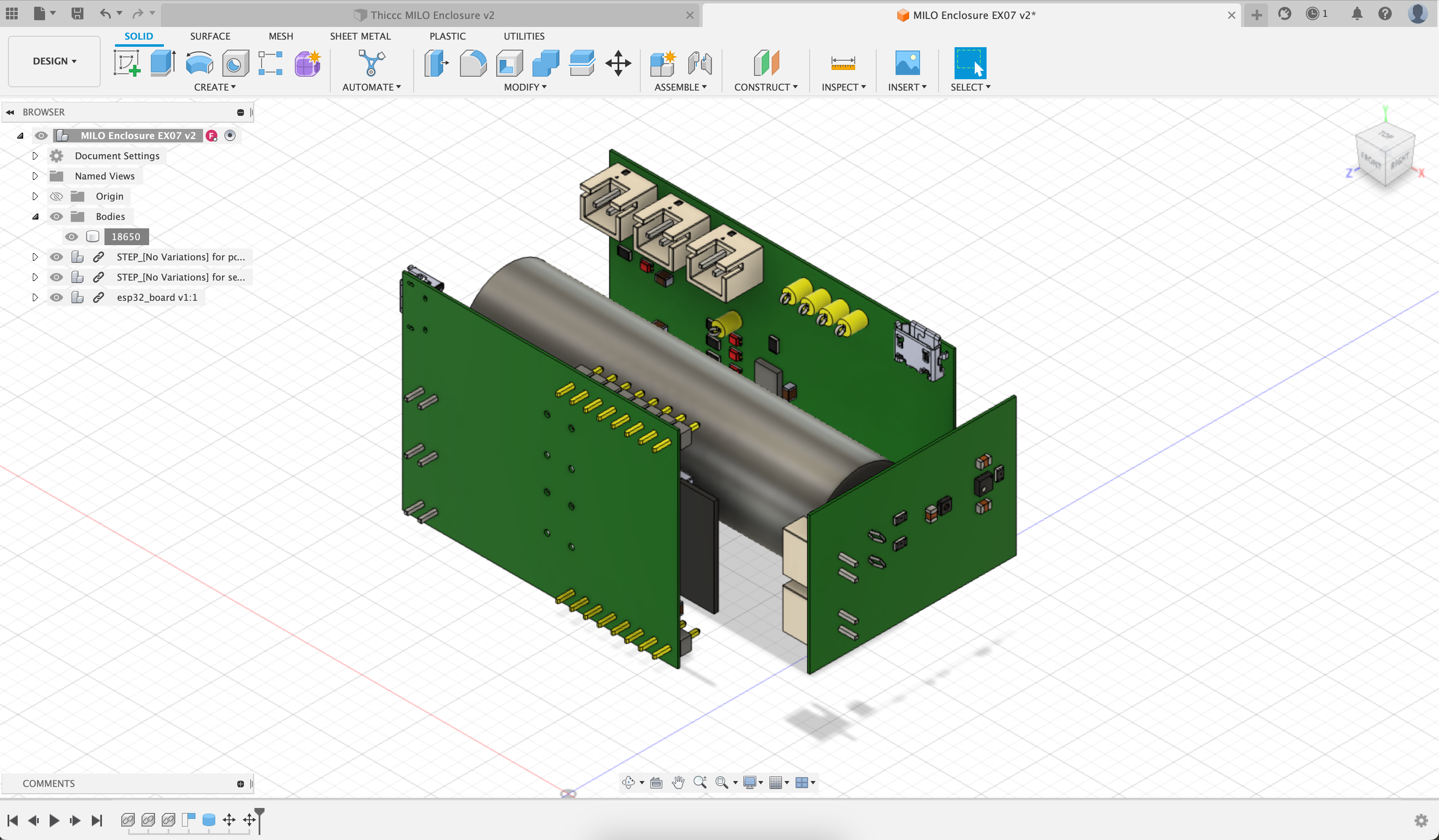
Move on once you're happy with how everything's oriented. Your CAD might look something like this afterwards:
Doing something sketchy
We'll define our enclosure geometry by sketching some 2D profile, and then extruding that into 3D. This is a pretty common design paradigm. The 2D profile we're creating our box from is called a sketch, and we'll define one around our little battery and PCB bundle. Hit Solid -> Create Sketch, and select and appropriate plane. Add a rectangle to this plane by hitting the R key (or by selecting a rectangle from the Sketch menu) and place it around our components - this will form the inside wall of the enclosure.
From here, you'll edit this sketch to add more geometry to our enclosure. You'll need to add the outer side wall, mounting holes, and any other geometry you'd like.
Here's what that might look like in the end - I added some extra material at the corners so that my mounting holes sit on the inside of the box. Make your walls at least 2mm thick so that we get some mechanical stiffness (and so my 3D printer doesn't turn your CAD into spaghetti).
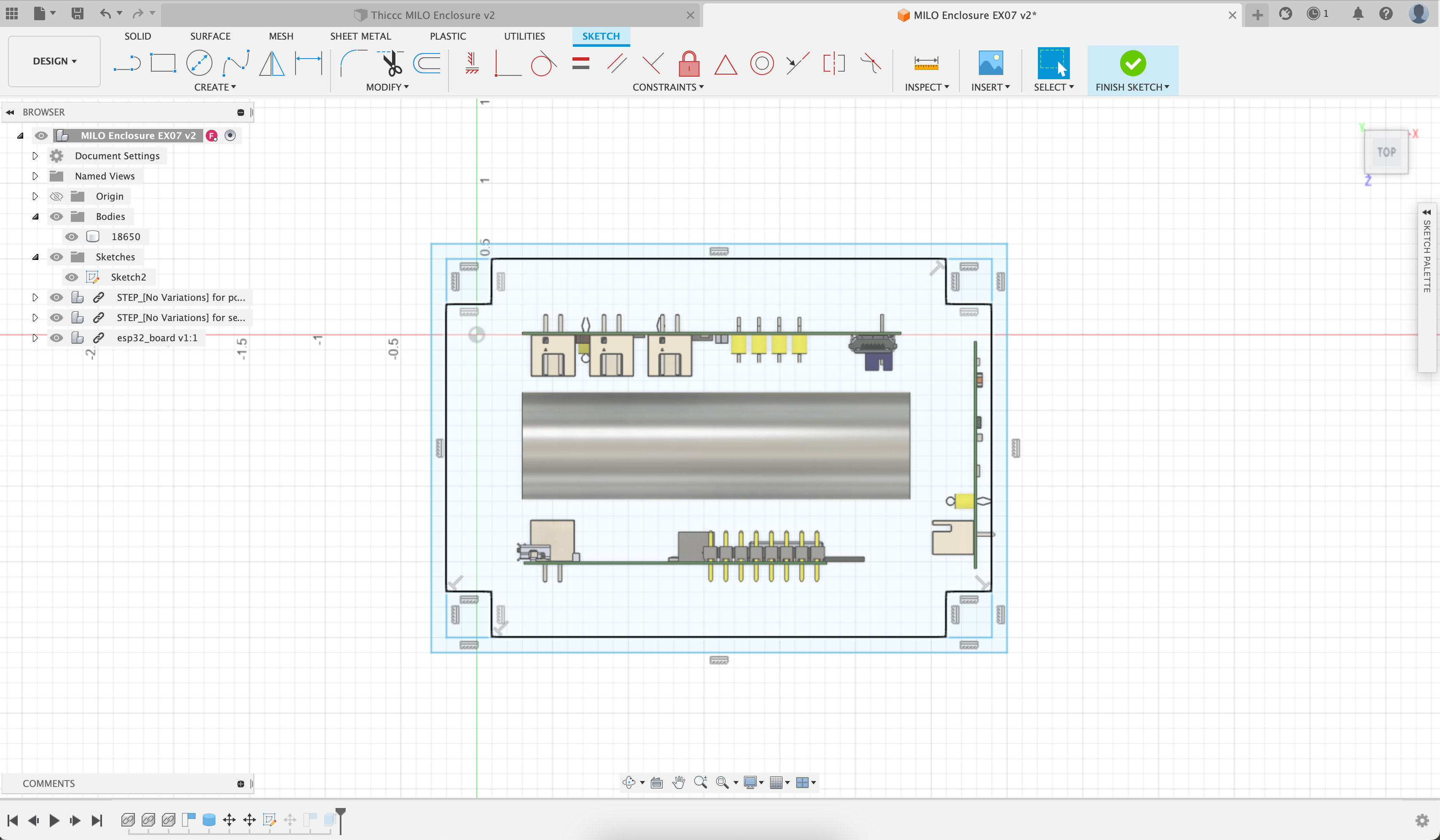
Here, I've decided to put all my boards on the sides of the enclosure - but you could just have easily put them all on one side, or on the bottom of your enclosure. And since the staff boards don't have mounting holes, I haven't included them in my design. But yours do, and you'll need to include them if you want to hold your boards in with them. Do what feels right for you 🤠.
I've also aligned all of my geometry to the default 0.1" grid that Fusion uses out of the box. This is for convenience - I can round my box dimensions up to the nearest 0.1" and still be okay. And that means that placing lines/rectangles/circles is way easier since I can just snap to the grid.
Extroooooooode
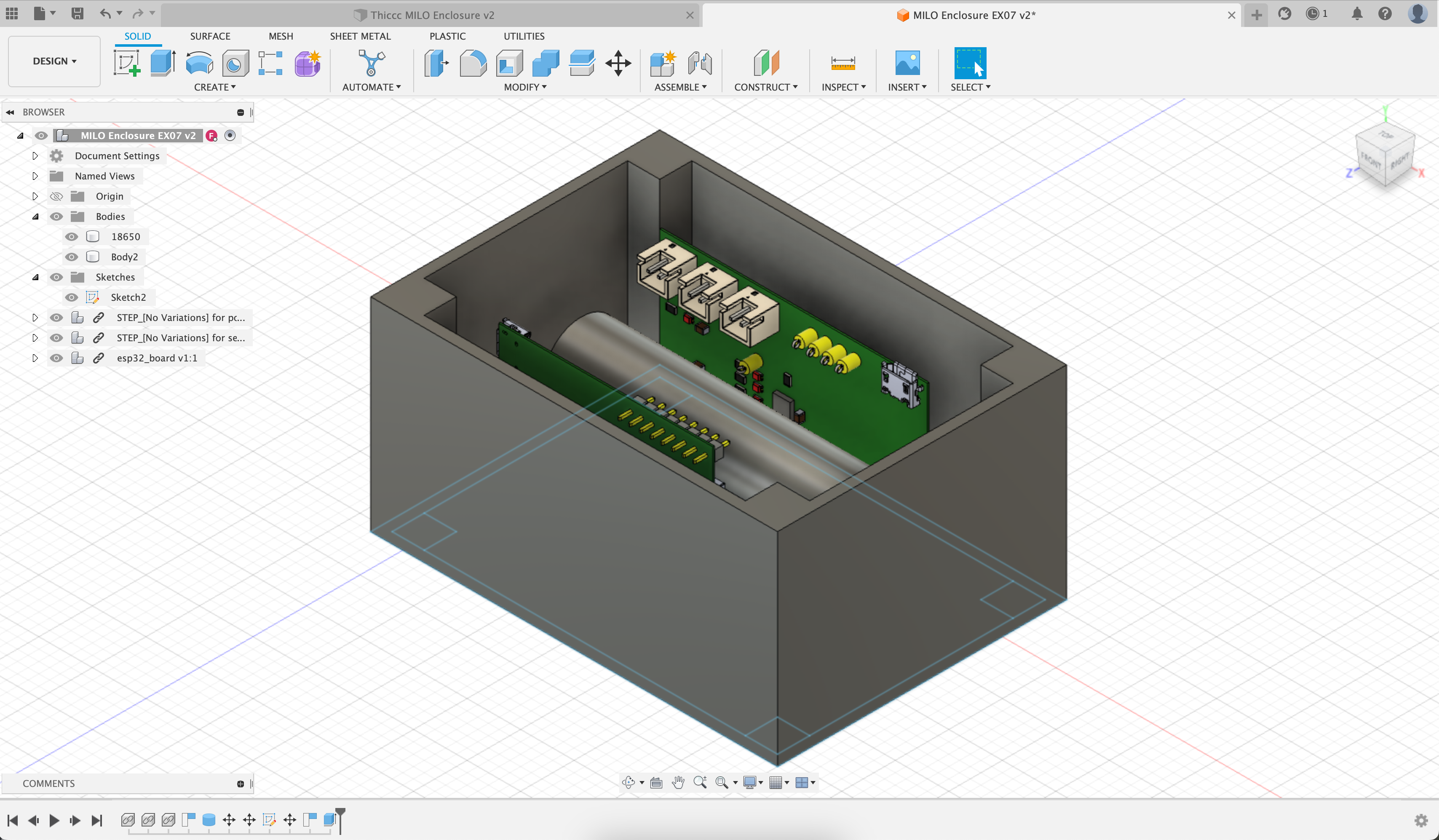
Now that we've got our 2D sketch defined, we'll want to extrude it into 3D geometry. Hit the Finish Sketch button to exit the sketch editor, and then hit Solid -> Extrude, and select the regions of the sketch you'd like to extrude, and how far you'd like to extrude them. Mine looks like this afterwards:
We'll repeat the same thing to make the bottom part of the enclosure. We'll select the parts of our sketch we'd like to extrude again - but we'll extrude downwards this time to make the bottom of the box. We'll do this the same way - if Fusion automatically hid your sketch and you can't select it, you might need to make it visible again by finding it under the Sketches folder in your editor and clicking the eyeball. And when you go to extrude downwards, make sure the Operation is set to Join, otherwise the geometry it makes won't get added to the rest of the enclosure.
Embossing Text
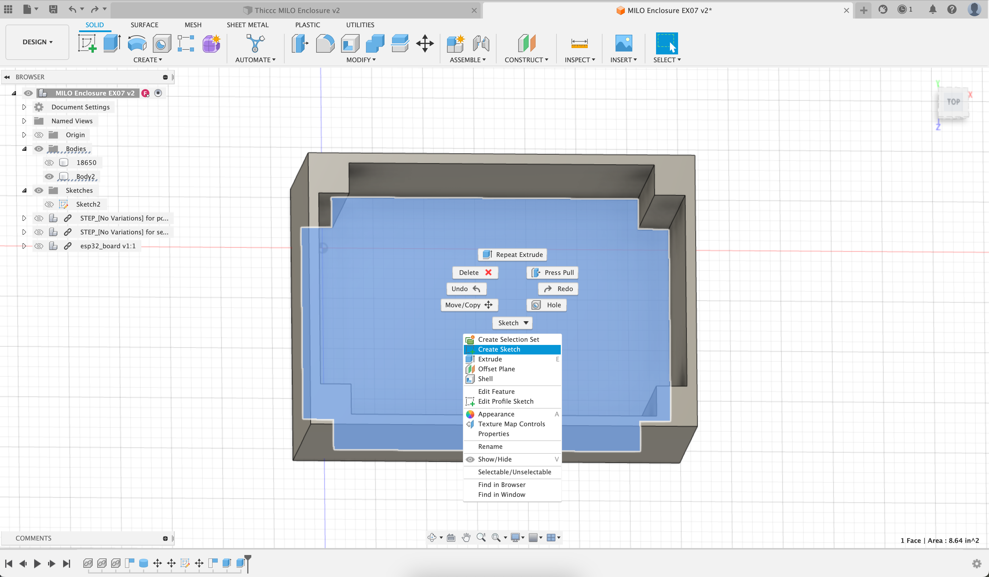
While we're here, we're going to want to label our enclosures to prevent them from getting mixed up. Since we'll be 3D printing these, we'll just emboss the text on the inside of the enclosure. Go ahead and hide the PCBs and battery from the design by finding the part in the folder tree on the side, and deselect the eyeball. Rotate the enclosure around so we're looking into it, select the top face of the bottom, right click, and hit Create Sketch:
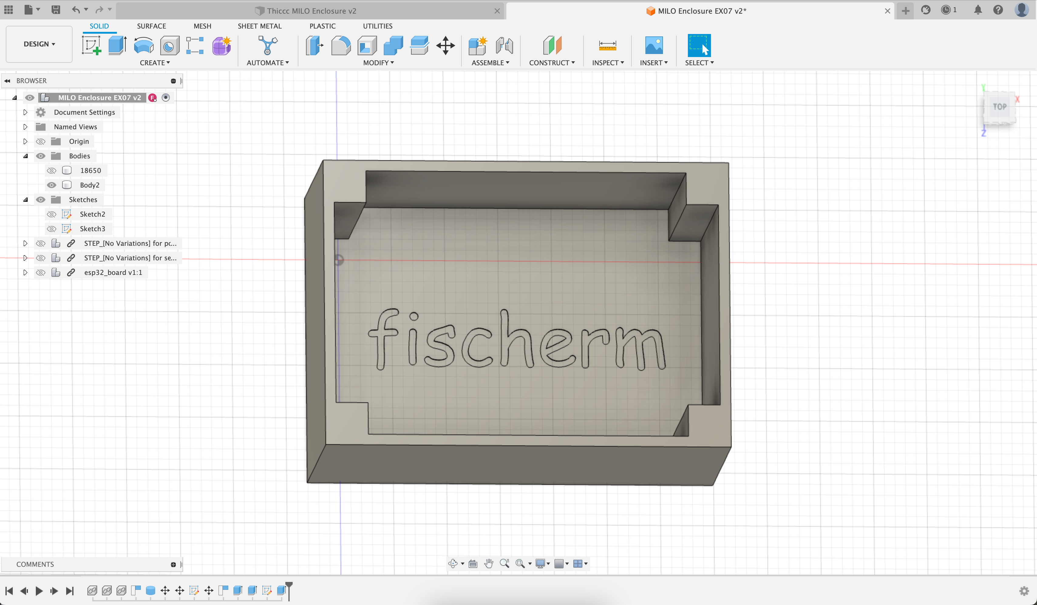
This will make a sketch on the face we've just selected. We'll emboss the text by adding some text to the sketch (Sketch -> Text) , and extruding downwards like before - which will cut out the text region from the underlying solid region. Add your kerberos with the text tool, which should look like:
Inserts
We've got a stash of heat set inserts that take a M3 screw - you're welcome to use those for your enclsoures. Since none of my boards have mounting holes, I'm not using them to hold the boards in, but I'm using them to hold the lid on. I'll need to make a 5mm diameter hole to fit the particular inserts we've got, and I'll need to make that hole recessed 5mm from the surface of the enclosure.
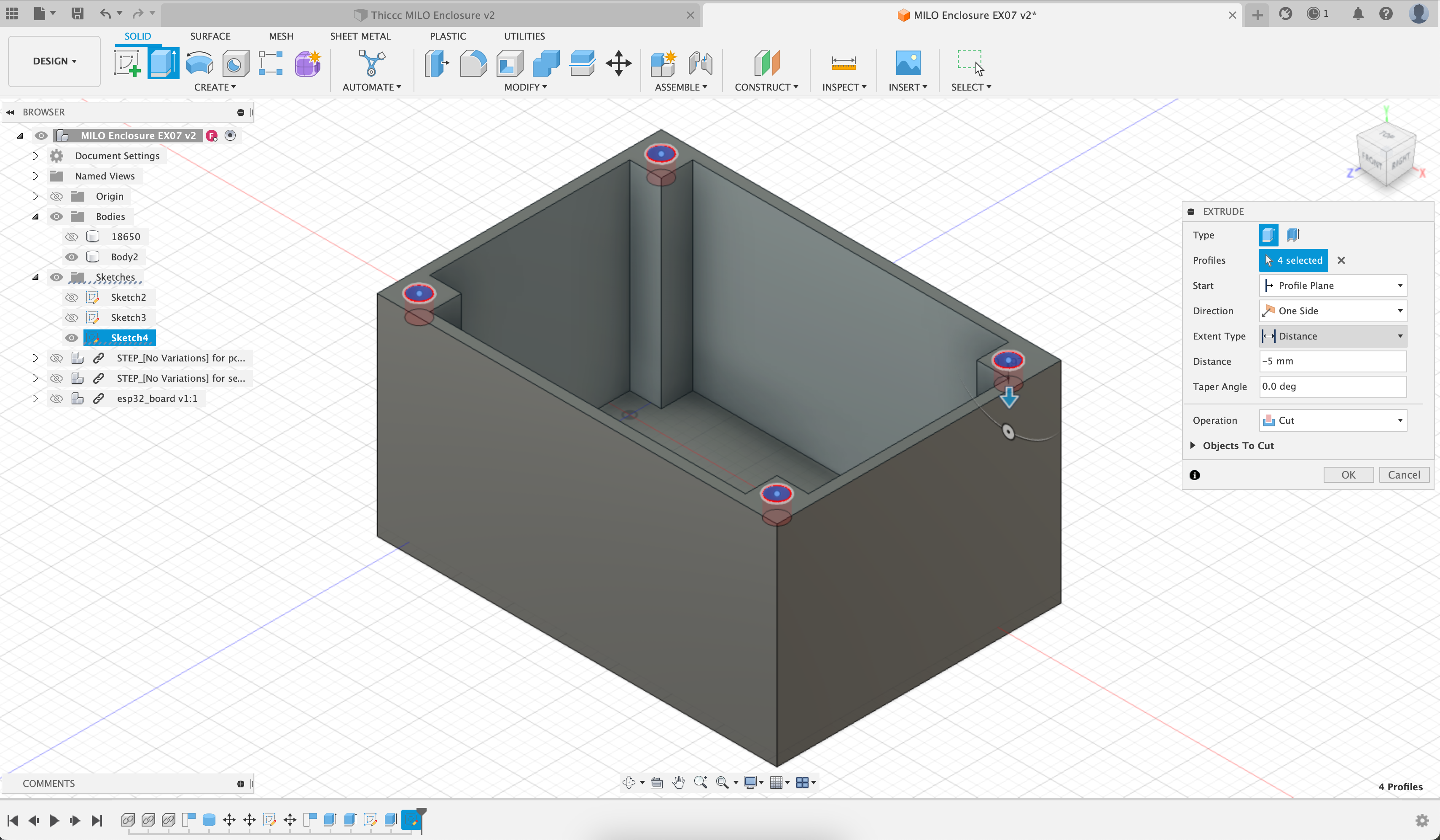
I'll add this to the enclosure by making a new sketch on the top of the enclosure (just like how we did the text embossing), adding some circles, and extruding them downwards, like so:
Sensor Cutout
We'll need a little vent to the atmosphere for the sensor to poke out through. We'll add these in exactly the same way as the insert holes and the text: adding a sketch on the face we want to modify, drawing the shape of the cutout we want, and extruding it through. Here's what that looks like:
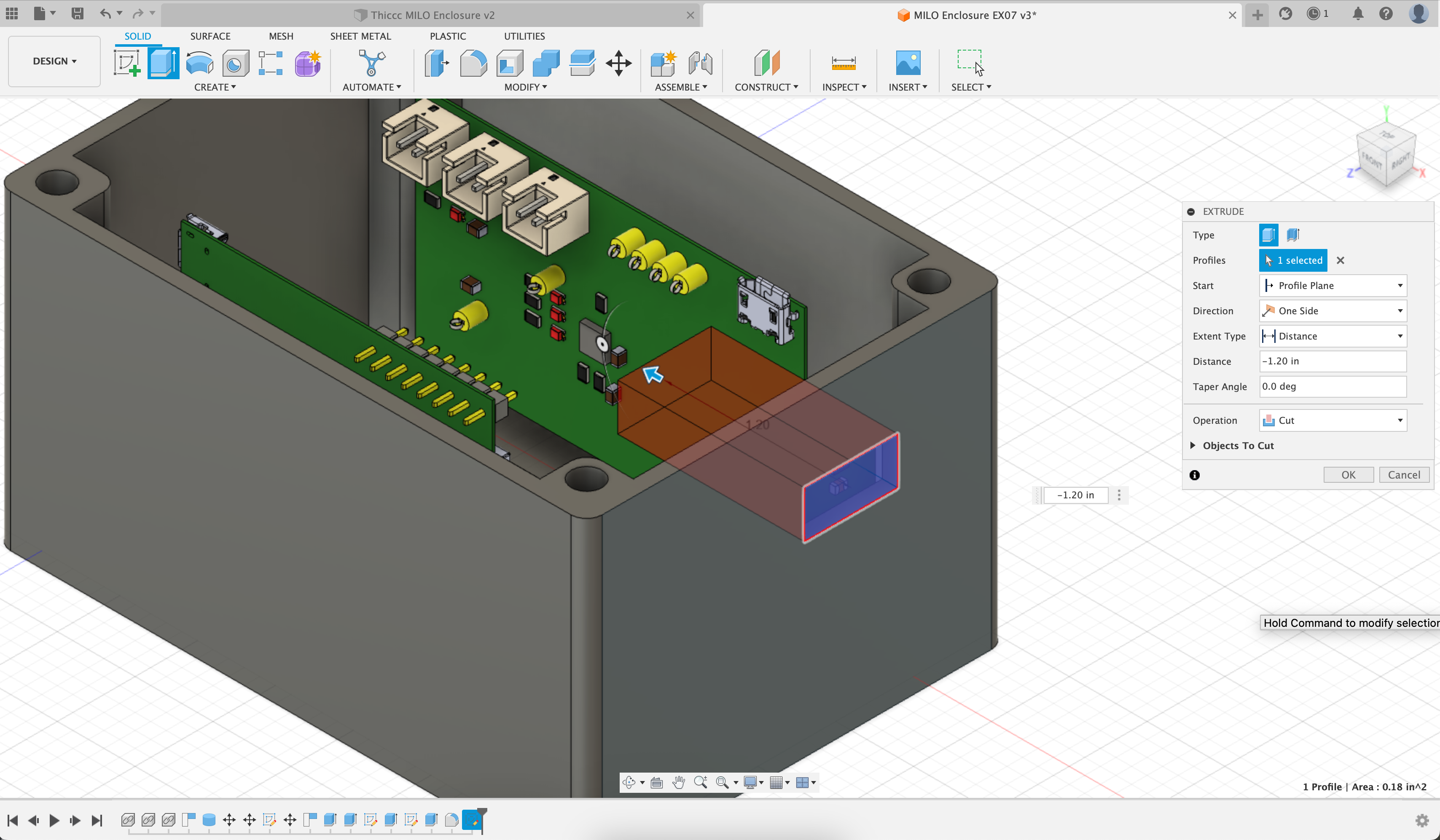
Don't make the cutout too wide, otherwise the 3D printer will have a hard time bridging the gap.
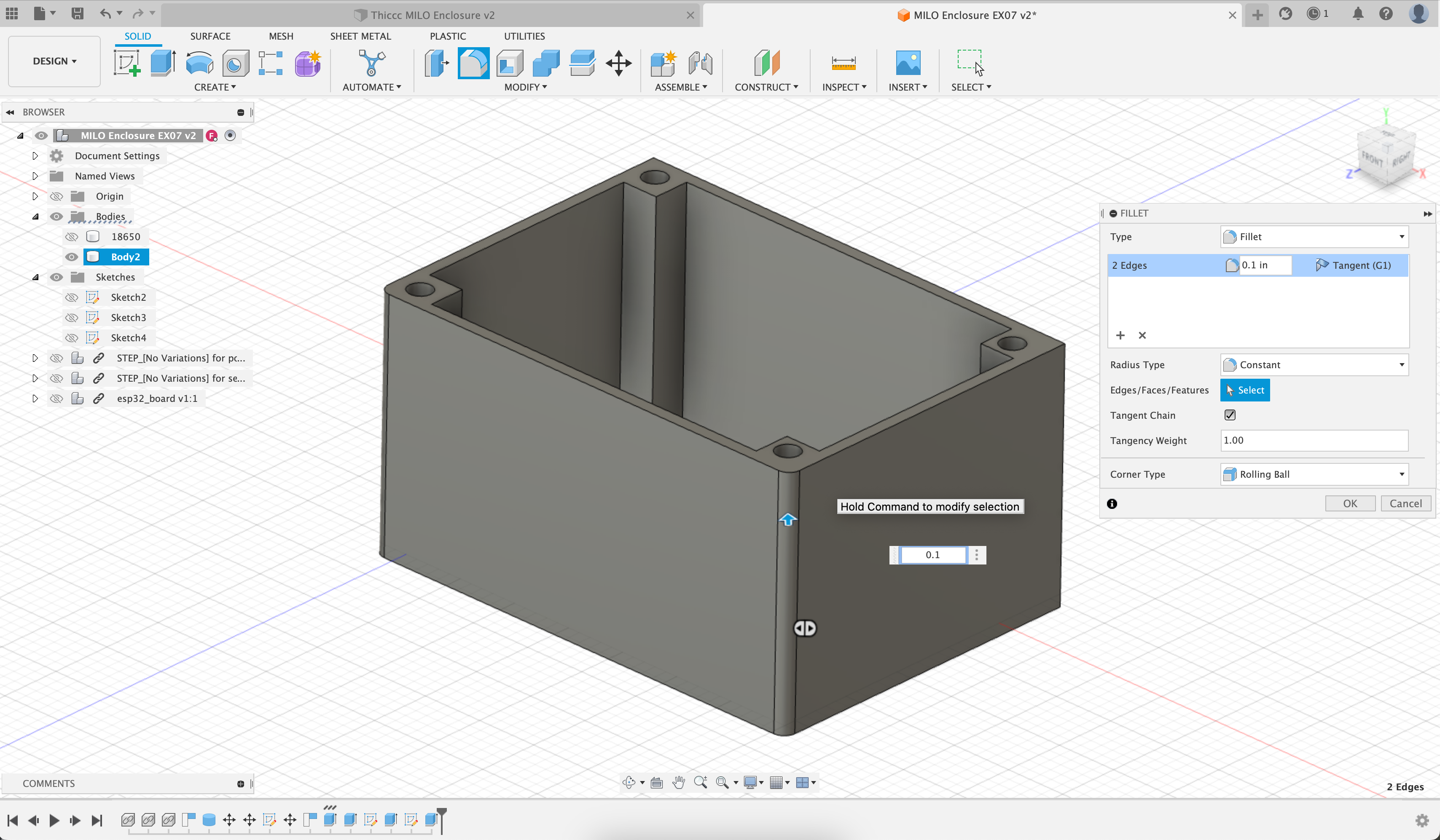
Fillet
No no no, not that kind. A fillet is just a rounded edge on some geometry, and you can optionally add them to your design to make it look a little prettier. The fillet tool is under the Modify menu, and you select the edges you'd like to round, along with a radius that specifies how hard you'd like to round them, like so:
Lid?
We'll let you figure out how to make the lid - the same pattern of extruding sketches into 3D geometry still works for the lid. As a hint, you can reuse one of your existing sketches, and just change the options when you extrude it 😉
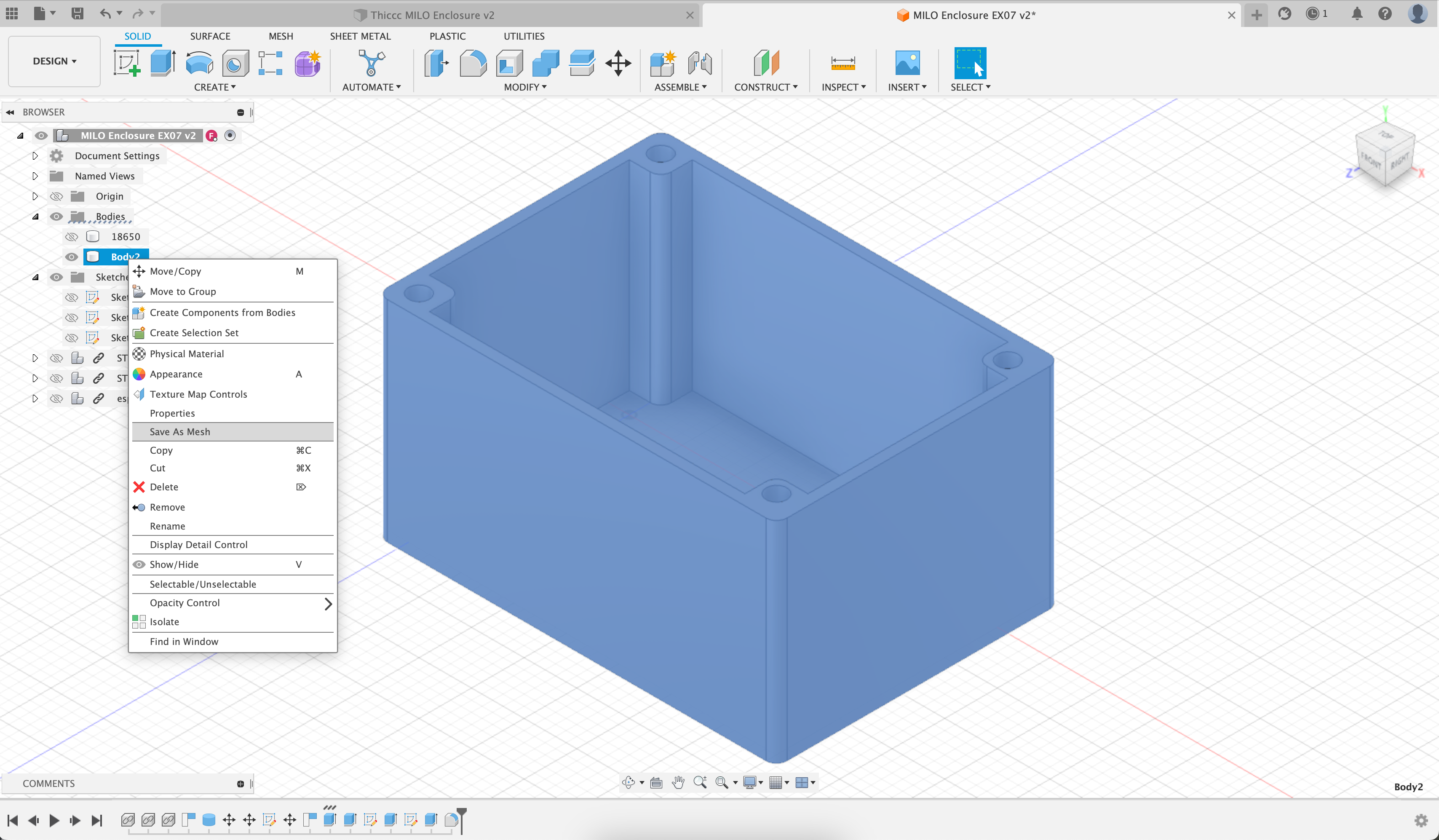
Mesh Generation
Once you've happy with your enclosure, save your file, and export the geometry as a 3D-printable mesh. The button for this can be found by selecting the geometry in the tree on the left, right clicking, and hitting Save as Mesh like so. The default options are fine - a file format of 3MF and Medium mesh refinement are perfect for us.
Do this for both the enclosure itself and the lid. Upload each in the submission boxes below:
Enclosure Mesh Submission

Lid Mesh Submission