Developing the MILO firmware
Please Log In for full access to the web site.
Note that this link will take you to an external site (https://shimmer.mit.edu) to authenticate, and then you will be redirected back to this page.
Firmware
In this problem set you will get the toolchain up and running for working with our embedded system of choice (the ESP32-C3 SOC). We will use VSCode since it is a reasonable editor as well as the Platform.io package and then finally, for ease of use, some Arduino hardware abstraction layer libraries.
From the class supplies grab:
- An ESP32-C3 XIAO board
- A USB cable that will work (note the ESP32-C3 breakout that we are using has a USB C type connector so depending on your computer you may need a different type of connector/cable. We have several types of adapters and cables to help with this)
- A SHTC3 temperature sensor breakout board
- A breadboard
- A good attitude
These should all be found in the lab kits handed out during lab04.
Software Installation
The first thing we need to do is download and install the software that we'll be using to work with our microcontroller. We could just use regular "Arduino" and its IDE, but it has aged horribly. So instead we'll use Visual Studio Code along with PlatformIO. While less hand-holdy than the Arduino IDE, VSCode in conjunction with Platformio is a far more usable development environment (minus a few annoyances), and essentially what is/could be used in industry.
M1 or M2 Mac Users!!
If you are on a M1 or M2 Mac from the last few years go into a terminal first and run:
softwareupdate --install-rosetta
Visual Studio Code (VS Code for short)
If you already have Visual Studio Code (note this is NOT the same thing as Visual Studio), you can skip to section 1.3 Visual Studio Code Extensions
We'll be using PlatformIO via a Visual Studio Code extension, so we'll first need to download VS Code. Go here and select the option for your operating system. Download and install it.
M1 or M2 Mac Users
Before opening VSCode, right click on it and click Get Info. In the dialog box, tick the Open using Rosetta option.
Note: This should help fix any chardet or arm64 and x86\_64 error messages. Ensure you quit VSCode and reopen it after making this change.
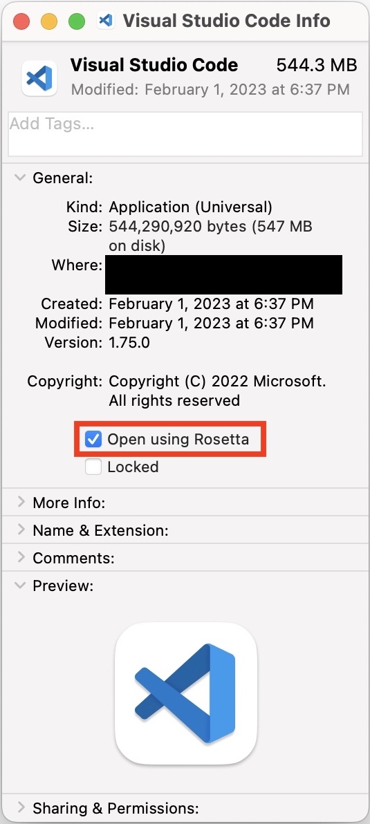
VSCode Get Info dialog box
Visual Studio Code Extensions
Once it's installed, open up Visual Studio Code. You may be greeted with some optional setup steps, you can ignore these.
Take a look at the sidebar all the way to the left. Select the fifth one from the top (if you hover over it, it'll say "Extensions").
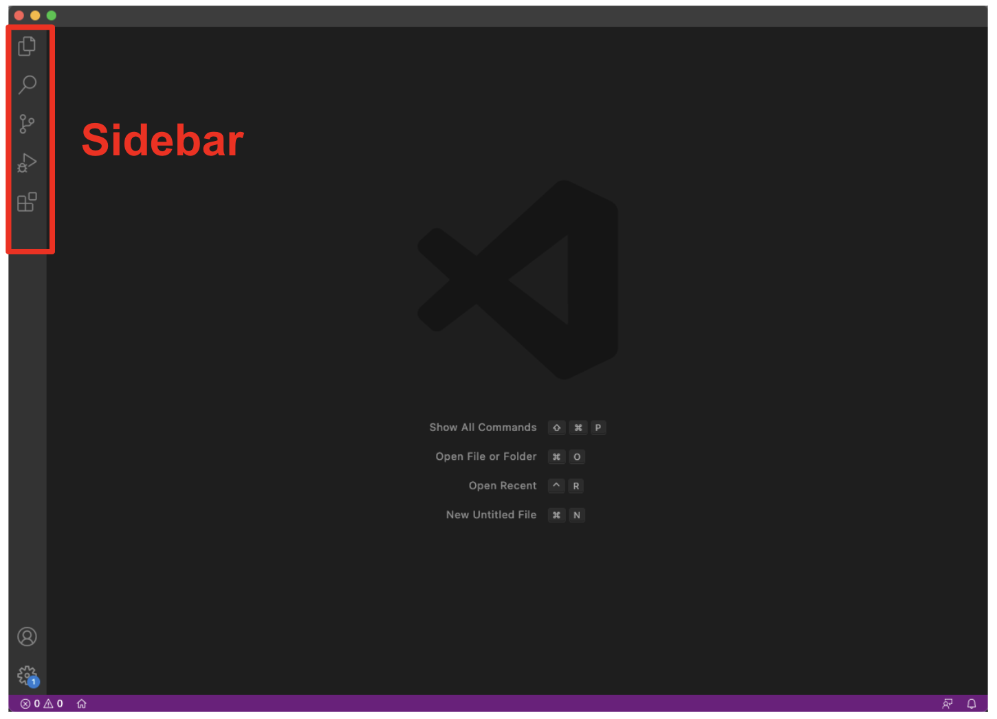
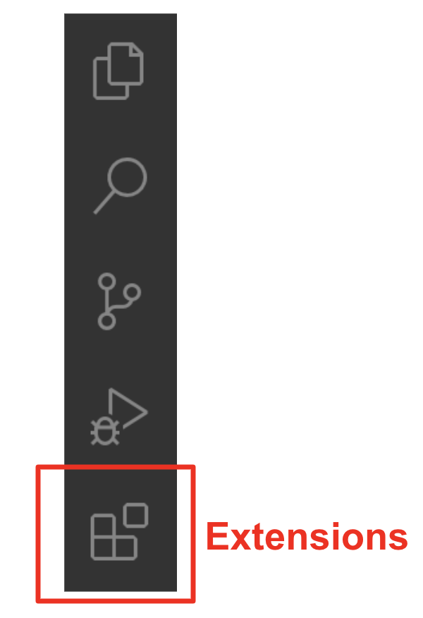
Visual Studio Code sidebar. "Extensions" is the last option from the top.
C/C++
When you click on that icon, a search bar should appear to the right of the sidebar. PlatformIO depends on Microsoft's C/C++ extension, so we need to install that. Type "C/C++" into the search bar and it should come up. It looks like this:
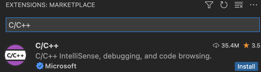
Select it, then click the blue "Install" button to install it.
PlatformIO
PlatformIO is the development environment we'll be using when doing the labs. It's offered as a Visual Studio Code extension, so we'll install it like we did the C/C++ extension. Type "PlatformIO" into the extensions search bar and this should come up:
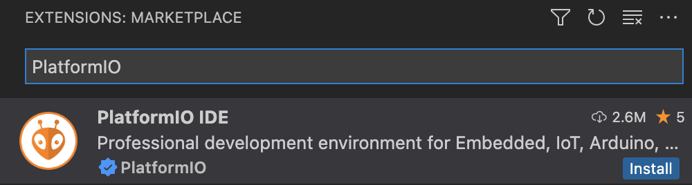
Select it and click "Install." Once it installs, restart Visual Studio Code (exit and reopen it). You should now have a new icon on your sidebar.

New PlatformIO Icon(!!)
Let's investigate. Click on the icon, and a menu should appear to the right of the sidebar. Click "Open" (the first option under the "PIO Home" section). Now, we should be on the PlatformIO home page! (If you are not, click on the little house in the bottom left corner of the screen, on the purple toolbar.)
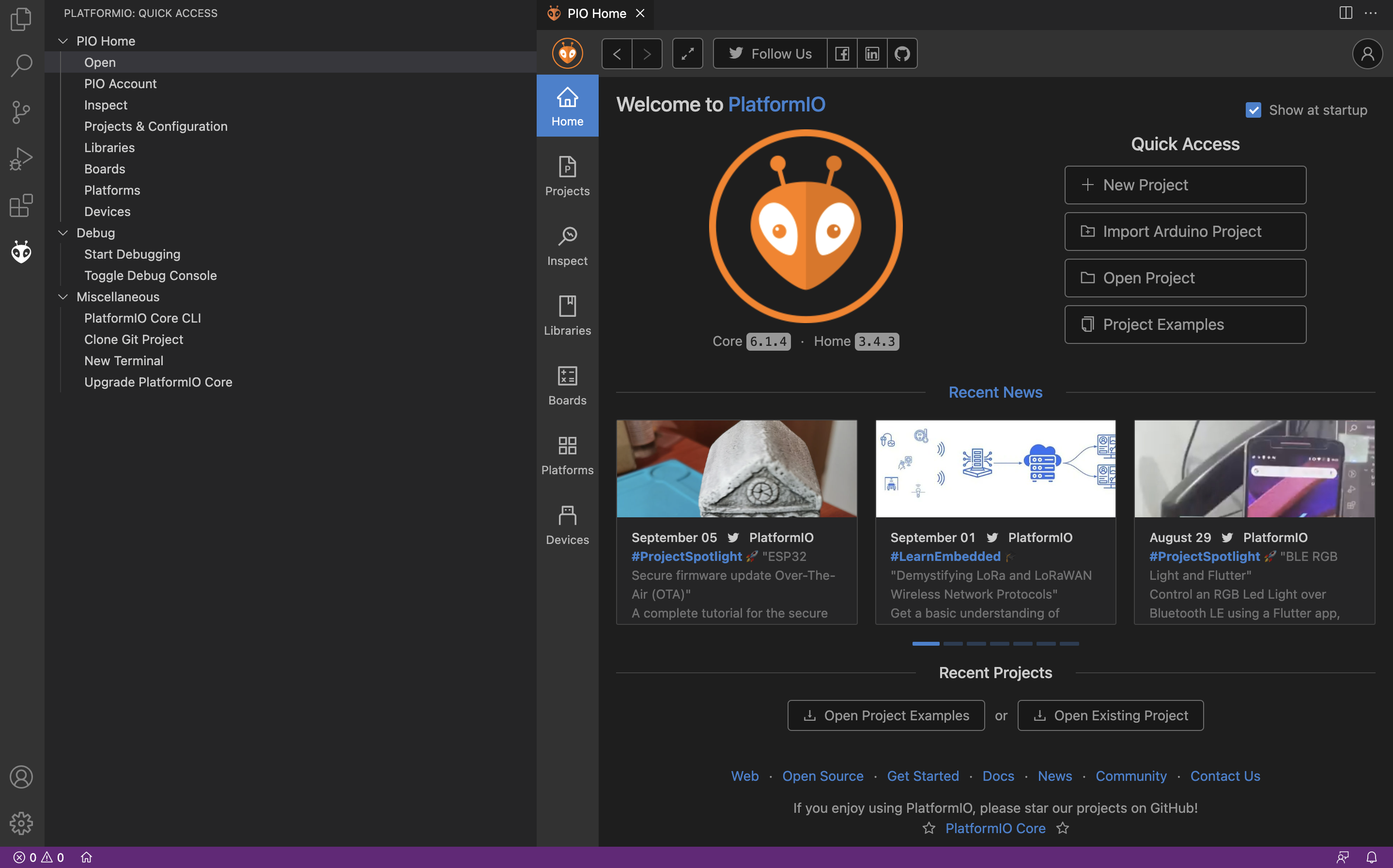
PlatformIO Homepage
Testing the Setup
Now let's actually get something running on our microcontroller to see if this all worked. If you haven't already, open up Visual Studio Code and go to the PlatformIO home page. Click on "New Project" and fill out the fields as follows:
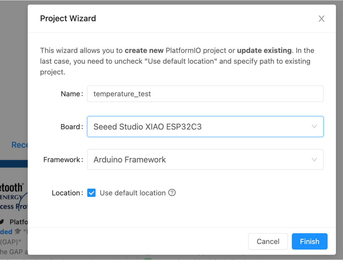
It is extremely important that you use the correct Board and Framework!
Click "Finish," and then you'll need to wait a few seconds to a few minutesfor initialization (you need to be connected to the Internet for this).
NOTE: You may encounter this error, saying that the project could not initialize:
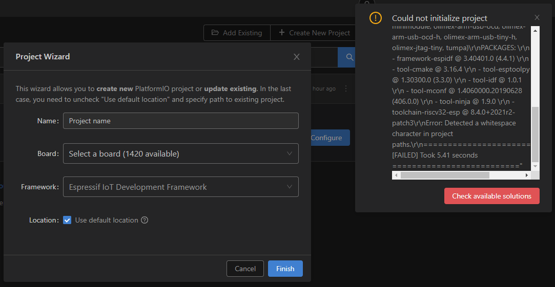
This happens if you have any white space characters in your project file path (for example, if your filepath was C:\Users\Brian Kernighan\...\project, the "Brian Kernighan" part would be a problem, since there's a space). To fix:
- Create a folder named
.platformioin yourC:\folder. - Restart Visual Studio Code
- Uncheck the "Use default location" box
- Save your project in a location where the path doesn't have a white space. For example, you could make a
6190-labsfolder in yourC:\and save everything there.
Once initialization is complete, you might get a pop-up asking "Do you trust the authors of the files in this folder?" Select "Yes."
Default project files
You should now see some files and folders on the left side of your screen (if you don't, click on the Explorer icon, which should be the top one on the sidebar).
platformio.ini, your project configuration file
The first file we'll look at is your platformio.ini file. This will be the configuration file for your project.
Find it in the sidebar, and open it. You should see these four lines:
[env:seeed_xiao_esp32c3]
platform = espressif32
board = seeed_xiao_esp32c3
framework = arduino
main.cpp, where your program lives
Click on the src folder, and you'll see a file named main.cpp. This is your "entry point" file. You can have other .cpp and .h files and include the, but your code will always "start" here. Instead of it being your standard int main(void) C-type function entry, we'll instead use the Arduino.h library to allow us to use the setup and loop functions common to that way of programming. As a reminder, since we'll assume you've all done some Arduino-type programming before:
setupruns once at the beginning of the program and we'll use it for a lot of initializations.loopruns continuously as fast as it can/we allow it. This is where the microcontroller will "live" most of the time.
Open main.cpp, delete the existing code, and copy and paste the following code into that main.c file.
#include <Arduino.h>

void setup() {
  Serial.begin(115200);
}

void loop() {
  char message[] = {0x48, 0x49, 0x20, 0x54, 0x48, 0x65, 0x52, 0x65,0x21,0xA};
  Serial.printf(message);
  delay(1000);
}
Let's "use" it. First, we need to build the code. Let's take a look at the blue toolbar at the bottom of the screen.
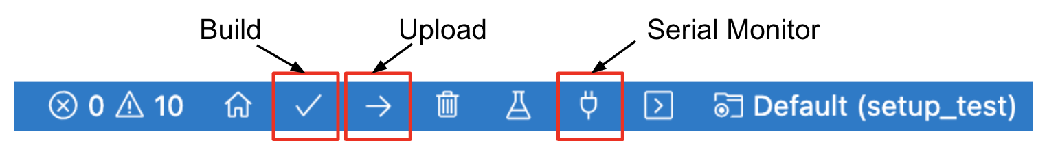
PlatformIO Toolbar
NOTE: If you can't see the toolbar, or it looks different, it may be because you have other VS Code workspaces open (this would only apply to people who have used VS Code previously). Removing those workspaces should fix that issue and get the toolbar to show up.
Build
Verify that you see Default(setup_test) like shown on the toolbar. For a given project, we need to make sure that field is Default(project_name) so that we're building/uploading the correct project. If there is nothing there, that means that you don't have a project open in your VS Code workspace; if it says something different (which may happen as you start to build new projects and move between different ones), you can change it by clicking on that part of the toolbar and selecting the correct project.
Now, click the check mark icon on the toolbar to build our program. If the code compiled successfully, you should see a message saying something like "[SUCCESS] Took 45 seconds" print out in the terminal.
Upload
Next, making sure that you have physically connected your ESP32 to your computer, click on the arrow icon on the toolbar to upload the program to the ESP32.
If everything worked, when you open up the serial monitor (the plug shaped symbol), after a litle bit, you should see a message being printed on repeat. It should be made of basic regular letters. What message are you seeing? Enter it in the box below to get credit.

If you don't see a message getting printed repeatedly in the serial monitor, please check in with a staff member in office hours or post on Piazza.
Adding A Sensor
Now let's:
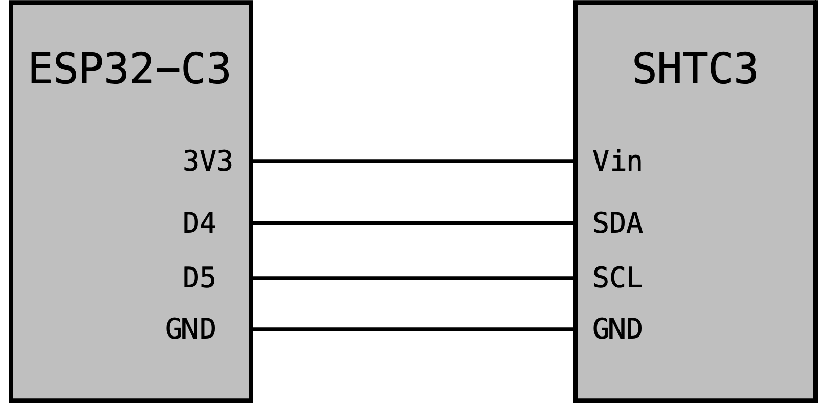
- Add a sensor (an SHTC3 Temperature and Relative Humidity sensor)
- Wire it to the ESP32C3 so that it can communicate over I2C
- Add a library to interface with that sensor
- Run some code to get the temp and humidity
In the previous section, the ESP could have been sitting wherever, but now we need to electrically interact with it. so make sure you solder header pins onto your ESP32-C3 if you haven't already. Then grab a SHTC3 breakout board. It will also need to have its pins soldered on (just like with the microcontroller).
Using a breadboard and some wires, wire it up like shown below (note you will find the getting started document helpful for pins).
We next need a library to communicate with the chip on this breakout board. Despite this being an Adafruit board, the library from Sparkfun is a little more lightweight and has less cross-dependencies so we'll use that instead. It can be found here. Download the whole repo, expand/decompress it, and then move it into the lib folder inside your platformio project. Note you just may need to use the File Manager or My Computer or something that is not VSCode to do that.
One that library is in place, replace the code in your main.cpp with:
#include <Arduino.h>
#include "SparkFun_SHTC3.h" // Click here to get the library: http://librarymanager/All#SparkFun_SHTC3
SHTC3 mySHTC3;              // Declare an instance of the SHTC3 class
//function stubs:
void errorDecoder(SHTC3_Status_TypeDef message);
void printInfo();

void setup() {
  Serial.begin(115200);      // Begin Serial
  while(Serial == false){};  // Wait for the serial connection to start up
  Serial.println("SHTC3 Example 1 - Basic Readings");    // Title
  Wire.begin();
  Serial.print("Beginning sensor. Result = ");  // Most SHTC3 functions return a variable of the type "SHTC3_Status_TypeDef" to indicate the status of their execution
  errorDecoder(mySHTC3.begin());  // To start the sensor you must call "begin()", the default settings use Wire (default Arduino I2C port)
  Serial.println();
  Serial.println("\n\n");
  Serial.println("Waiting for 5 seconds so you can read this info ^^^");

  delay(5000);                                                // Give time to read the welcome message and device ID.
}

void loop() {
  SHTC3_Status_TypeDef result = mySHTC3.update();             // Call "update()" to command a measurement, wait for measurement to complete, and update the RH and T members of the object
  printInfo();                                                // This function is used to print a nice little line of info to the serial port
  delay(190);                                                 // Delay for the data rate you want - note that measurements take ~10 ms so the fastest data rate is 100 Hz (when no delay is used)
}

///////////////////////
// Utility Functions //
///////////////////////
void errorDecoder(SHTC3_Status_TypeDef message){
  switch(message){
    case SHTC3_Status_Nominal : Serial.print("Nominal"); break;
    case SHTC3_Status_Error : Serial.print("Error"); break;
    case SHTC3_Status_CRC_Fail : Serial.print("CRC Fail"); break;
    default : Serial.print("Unknown return code"); break;
  }
}

void printInfo(){
  if(mySHTC3.lastStatus == SHTC3_Status_Nominal){
    Serial.print("RH = ");
    Serial.print(mySHTC3.toPercent()); // "toPercent" returns the percent humidity as a floating point number
    Serial.print("%, T = ");
    Serial.print(mySHTC3.toDegF());   // "toDegF" and "toDegC" return the temperature as a flaoting point number in deg F and deg C respectively
    Serial.println(" deg F");
  }
  else{
    Serial.print("Update failed, error: ");
    errorDecoder(mySHTC3.lastStatus);
    Serial.println();
  }
}
Compile and upload and look at the serial monitor. If all is well (wiring, library, etc.) you should see the humidity and temperature printing out like so (obviously different based on where you are at on this big blue marble which we only have one of don't you know so let's take care of it)
RH = 30.62%, T = 73.61 deg F
RH = 30.61%, T = 73.59 deg F
RH = 30.59%, T = 73.64 deg F
RH = 30.57%, T = 73.59 deg F
...
If it isn't printing or giving errors in readout, double check your wiring, and all the other usual suspects one would think about with a sysytem like this. Also, of course, reach out for help on Piazza or with staff!
Touching the Cloud
Ok instead of having our device read a local sensor, let's instead talk to a remote computational device via the internet. Let's replace our code with the code below:
Note a few things:
- There's a lot more going on in this code than the previous two. (It is basically a modified version of some 6.08 code from a lab).
- This code connects to the WiFi. This requires you to put in the valid credentials for a 2.4GHz network. The good ones on the 5th floor lab space (hopefully where you are) are either
EECS_Labs(with no password) or608_24Gwith password608g2020. You cannot use WiFi that requires some sort of weird authorization like the new MIT networks, so if that's your situation, come to lab or hotspot or find another network. - Once connected this code will send simple HTTP GET requests to aremote server that provides number-based facts in response (we did this in 6.08 for those of you who took that class previously).
#include <Arduino.h>
#include <WiFi.h> //Connect to WiFi Network
#include <SPI.h> //Used in support of TFT Display
#include <string.h>  //used for some string handling and processing.

void do_http_GET(char* host, char* request, char* response, uint16_t response_size, uint16_t response_timeout, uint8_t serial);
uint8_t char_append(char* buff, char c, uint16_t buff_size);

const int RESPONSE_TIMEOUT = 6000; //ms to wait for response from host
const int GETTING_PERIOD = 5000; //periodicity of getting a number fact.
const uint16_t IN_BUFFER_SIZE = 1000; //size of buffer to hold HTTP request
const uint16_t OUT_BUFFER_SIZE = 1000; //size of buffer to hold HTTP response
char request_buffer[IN_BUFFER_SIZE]; //char array buffer to hold HTTP request
char response_buffer[OUT_BUFFER_SIZE]; //char array buffer to hold HTTP response

uint32_t loop_controller; //used for timing
uint32_t last_time; //used for timing

//wifi network credentials for 6.08 Lab (this is a decent 2.4 GHz router that we have set up...try to only use for our ESP32s)
char network[] = "608_24G";
char password[] = "608g2020";

uint8_t scanning = 0;//set to 1 if you'd like to scan for wifi networks (see below):
/* For later use when doing wifi development at home or in dorm:
    Having network issues since there are 50 MIT and MIT_GUEST networks?. Do the following:
    When the access points are printed out at the start, find a particularly strong one that you're targeting.
    Let's say it is an MIT one and it has the following entry:
   . 4: MIT, Ch:1 (-51dBm)  4:95:E6:AE:DB:41
   Do the following...set the variable channel below to be the channel shown (1 in this example)
   and then copy the MAC address into the byte array below like shown.  Note the values are rendered in hexadecimal
   That is specified by putting a leading 0x in front of the number. We need to specify six pairs of hex values so:
   a 4 turns into a 0x04 (put a leading 0 if only one printed)
   a 95 becomes a 0x95, etc...
   see starting values below that match the example above. Change for your use:
   Finally where you connect to the network, comment out
     WiFi.begin(network, password);
   and uncomment out:
     WiFi.begin(network, password, channel, bssid);
   This will allow you target a specific router rather than a random one!
*/
uint8_t channel = 1; //network channel on 2.4 GHz
byte bssid[] = {0x04, 0x95, 0xE6, 0xAE, 0xDB, 0x41}; //6 byte MAC address of AP you're targeting.


void setup() {
  Serial.begin(115200); //begin serial
  if (scanning){
    int n = WiFi.scanNetworks();
    Serial.println("scan done");
    if (n == 0) {
      Serial.println("no networks found");
    } else {
      Serial.print(n);
      Serial.println(" networks found");
      for (int i = 0; i < n; ++i) {
        Serial.printf("%d: %s, Ch:%d (%ddBm) %s ", i + 1, WiFi.SSID(i).c_str(), WiFi.channel(i), WiFi.RSSI(i), WiFi.encryptionType(i) == WIFI_AUTH_OPEN ? "open" : "");
        uint8_t* cc = WiFi.BSSID(i);
        for (int k = 0; k < 6; k++) {
          Serial.print(*cc, HEX);
          if (k != 5) Serial.print(":");
          cc++;
        }
        Serial.println("");
      }
    }
  }
  delay(100); //wait a bit (100 ms)
  //if using regular connection use line below:
  WiFi.begin(network, password);
  //if using channel/mac specification for crowded bands use the following:
  //WiFi.begin(network, password, channel, bssid);
  uint8_t count = 0; //count used for Wifi check times
  Serial.print("Attempting to connect to ");
  Serial.println(network);
  while (WiFi.status() != WL_CONNECTED && count < 6) { //can change this to more attempts
    delay(500);
    Serial.print(".");
    count++;
  }
  delay(2000);  //acceptable since it is in the setup function.
  if (WiFi.isConnected()) { //if we connected then print our IP, Mac, and SSID we're on
    Serial.println("CONNECTED!");
    Serial.printf("%d:%d:%d:%d (%s) (%s)\n", WiFi.localIP()[3], WiFi.localIP()[2],
                  WiFi.localIP()[1], WiFi.localIP()[0],
                  WiFi.macAddress().c_str() , WiFi.SSID().c_str());
    delay(500);
  } else { //if we failed to connect just Try again.
    Serial.println("Failed to Connect :/  Going to restart");
    Serial.println(WiFi.status());
    ESP.restart(); // restart the ESP (proper way)
  }
  randomSeed(analogRead(A0)); //"seed" random number generator
}

/*-----------------------------------
  Generate a request to the numbersapi server for a random number
  Display the response both on the TFT and in the Serial Monitor
*/
void loop() {
  if ((millis() - last_time) > GETTING_PERIOD) { // GETTING_PERIOD since last lookup? Look up again
    //formulate GET request...first line:
    sprintf(request_buffer, "GET http://numbersapi.com/%d/trivia HTTP/1.1\r\n", random(200));
    strcat(request_buffer, "Host: numbersapi.com\r\n"); //add more to the end
    strcat(request_buffer, "\r\n"); //add blank line!
    //submit to function that performs GET.  It will return output using response_buffer char array
    do_http_GET("numbersapi.com", request_buffer, response_buffer, OUT_BUFFER_SIZE, RESPONSE_TIMEOUT, true);
    Serial.println(response_buffer); //print to serial monitor
    last_time = millis();//remember when this happened so we perform next lookup in GETTING_PERIOD milliseconds
  }
}


/*----------------------------------
   char_append Function:
   Arguments:
      char* buff: pointer to character array which we will append a
      char c:
      uint16_t buff_size: size of buffer buff

   Return value:
      boolean: True if character appended, False if not appended (indicating buffer full)
*/
uint8_t char_append(char* buff, char c, uint16_t buff_size) {
  int len = strlen(buff);
  if (len > buff_size) return false;
  buff[len] = c;
  buff[len + 1] = '\0';
  return true;
}

/*----------------------------------
   do_http_GET Function:
   Arguments:
      char* host: null-terminated char-array containing host to connect to
      char* request: null-terminated char-arry containing properly formatted HTTP GET request
      char* response: char-array used as output for function to contain response
      uint16_t response_size: size of response buffer (in bytes)
      uint16_t response_timeout: duration we'll wait (in ms) for a response from server
      uint8_t serial: used for printing debug information to terminal (true prints, false doesn't)
   Return value:
      void (none)
*/
void do_http_GET(char* host, char* request, char* response, uint16_t response_size, uint16_t response_timeout, uint8_t serial) {
  WiFiClient client; //instantiate a client object
  if (client.connect(host, 80)) { //try to connect to host on port 80
    if (serial) Serial.print(request);//Can do one-line if statements in C without curly braces
    client.print(request);
    memset(response, 0, response_size); //Null out (0 is the value of the null terminator '\0') entire buffer
    uint32_t count = millis();
    while (client.connected()) { //while we remain connected read out data coming back
      client.readBytesUntil('\n', response, response_size);
      if (serial) Serial.println(response);
      if (strcmp(response, "\r") == 0) { //found a blank line! (end of response header)
        break;
      }
      memset(response, 0, response_size);
      if (millis() - count > response_timeout) break;
    }
    memset(response, 0, response_size);  //empty in prep to store body
    count = millis();
    while (client.available()) { //read out remaining text (body of response)
      char_append(response, client.read(), OUT_BUFFER_SIZE);
    }
    if (serial) Serial.println(response);
    client.stop();
    if (serial) Serial.println("-----------");
  } else {
    if (serial) Serial.println("connection failed :/");
    if (serial) Serial.println("wait 0.5 sec...");
    client.stop();
  }
}
Upload the code. In the serial monitor, you should see random number facts printing out every few seconds. Your ESP32 does not internally contain all those facts, so the only way it could be printing those would be if it was getting them through the "ether"...so WiFi must be working. Nice. If you have that, that means you're good to move on!
Setting the Stage
Now let's set the stage for the next part...and point our ESP32-C3 to a as-yet-not-constructed server called ERROR. There's nothing "there" yet, but let's just set it up so it starts asking that server for information. Update your loop function like shown (either bulk copy-n-replace or find/replace the three changed lines like you would do in a Ranger Rick children's magazine):
void loop() {
  if ((millis() - last_time) > GETTING_PERIOD) { // GETTING_PERIOD since last lookup? Look up again
    //formulate GET request...first line:
    sprintf(request_buffer, "GET http://ERROR HTTP/1.1\r\n");
    strcat(request_buffer, "Host: ERROR\r\n"); //add more to the end
    strcat(request_buffer, "\r\n"); //add blank line!
    //submit to function that performs GET.  It will return output using response_buffer char array
    do_http_GET("ERROR", request_buffer, response_buffer, OUT_BUFFER_SIZE, RESPONSE_TIMEOUT, true);
    Serial.println(response_buffer); //print to serial monitor
    last_time = millis();//remember when this happened so we perform next lookup in GETTING_PERIOD milliseconds
  }
}
Recompile the code, reupload, and then see what happens in the serial monitor. Eventually, your code should repeatedly start printing this:
connection failed :/
wait 0.5 sec...
While ending on failure might not seem good, it is really just setting us up for the next part. Let's go and set up a server where our ESP32 is looking. this will fix it so we won't be failing to connect!